Integration Guide
This section provides the complete process for integrating and using the YOMOV SDK.
There are two integration options:
-
YOMOV SDK Core + YOMOV SDK Creator
-
YOMOV SDK Core only
How the integration options differ:
In addition to its developer productivity features, YOMOV SDK Creator includes YOMOV Multiplayer Sync and related capabilities.
Multiplayer synchronization is essential in LBE VR and is closely coupled with avatar animation, hand interaction, LBE paths, and multi-application bridging. Although Multiplayer Sync is not required for distribution through the YOMOV platform, we strongly recommend YOMOV Multiplayer Sync when your content does not implement custom multiplayer gameplay. This stable solution has been validated across dozens of LBE VR titles and hundreds of venues, helping maximize multiplayer stability while significantly reducing integration and debugging effort.
Workflow A: Use YOMOV Multiplayer Sync
Full integration walkthrough video:
Step 1: Initial Setup
SDK initialization loads underlying packages and configuration, connects to the Playback Control System, performs playback authorization, and loads the LBE path. These capabilities form the foundation of YOMOV LBE distribution.
-
In YOMOV SDK > Setting, enable Multiplayer Sync.
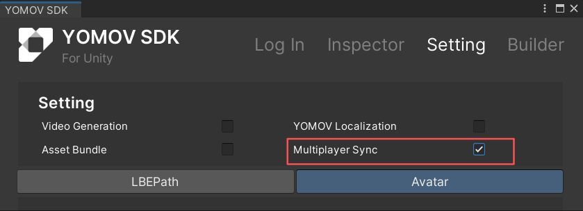
-
Add the YOMOV initialization component
- Open your VR application's initialization scene. From the YOMOV SDK menu, click Create YOMOVInitial.
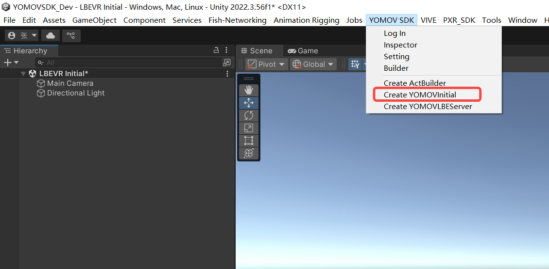
Add YOMOVInitial to the initialization scene
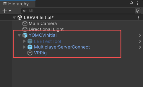
YOMOVInitial added
-
Bind XR Origin features
-
Open the generated YOMOVInitial Prefab Variant. Drag the application's XR Origin GameObject under YOMOVInitial > VRRig. We recommend using the hand-interaction variant provided by XRI.
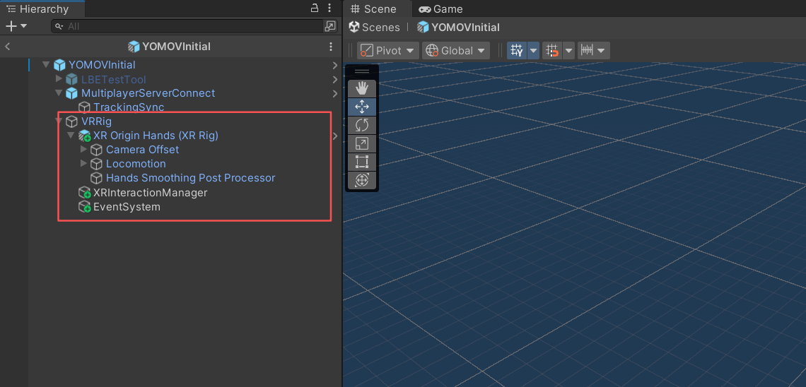
Place XR Origin under the VRRig node
-
Select the VRRig GameObject under YOMOVInitial. In the AddLBEInterator component, click Add LBE Interactor to add the components required for LBE path interaction to XROrigin.
- This provides the interaction effect that moves a player into the Void Space after leaving the content boundary.
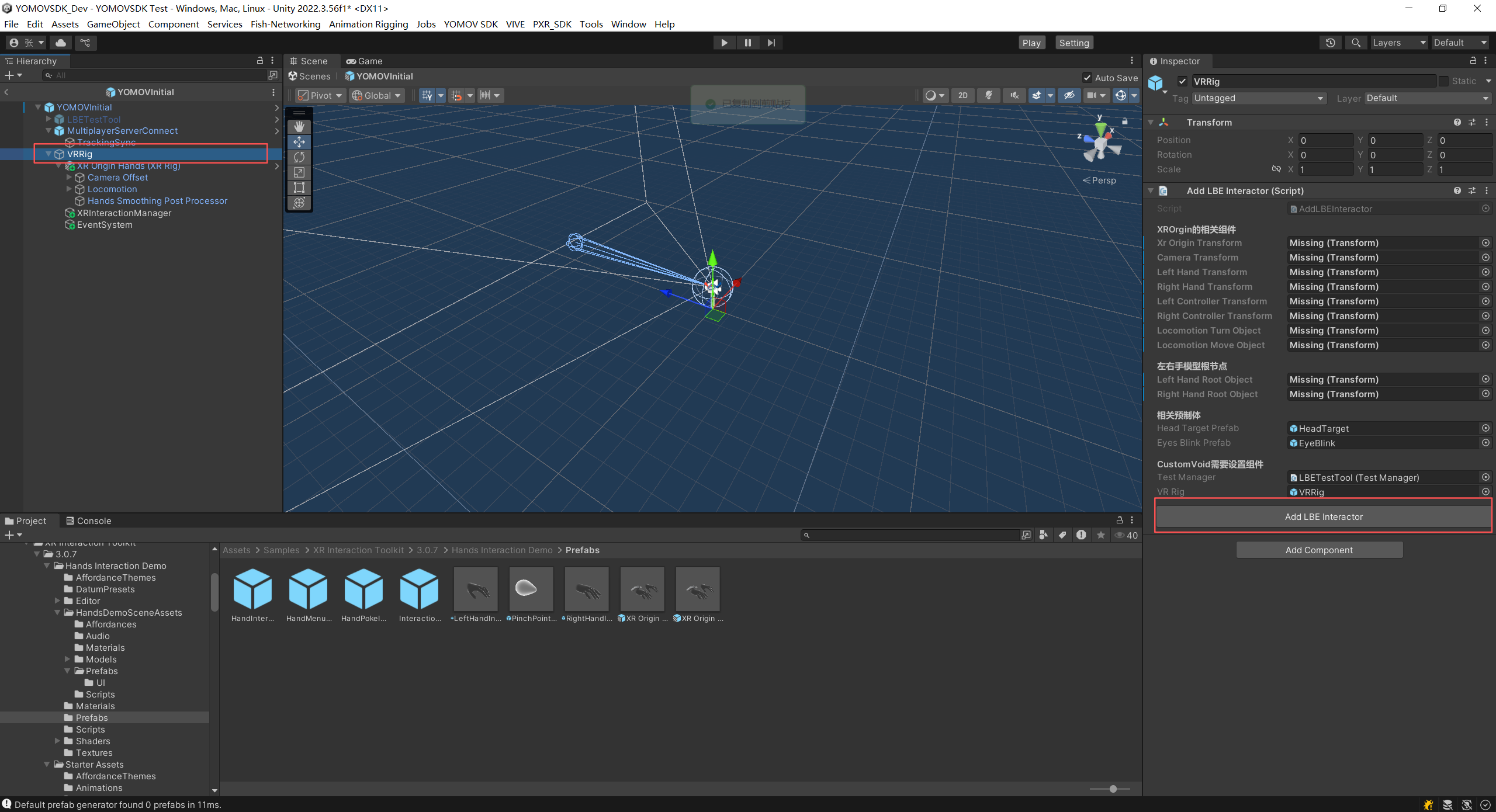
Add LBE Interactor action
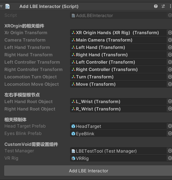
Components added successfully
-
Select the MultiplayerServerConnect GameObject under YOMOVInitial. In the BindXROriginData component, click Bind XROrigin Data to bind XROrigin pose and hand-tracking data to the multiplayer synchronization components.
- This synchronizes each player's pose and hand-tracking data through the multiplayer server.
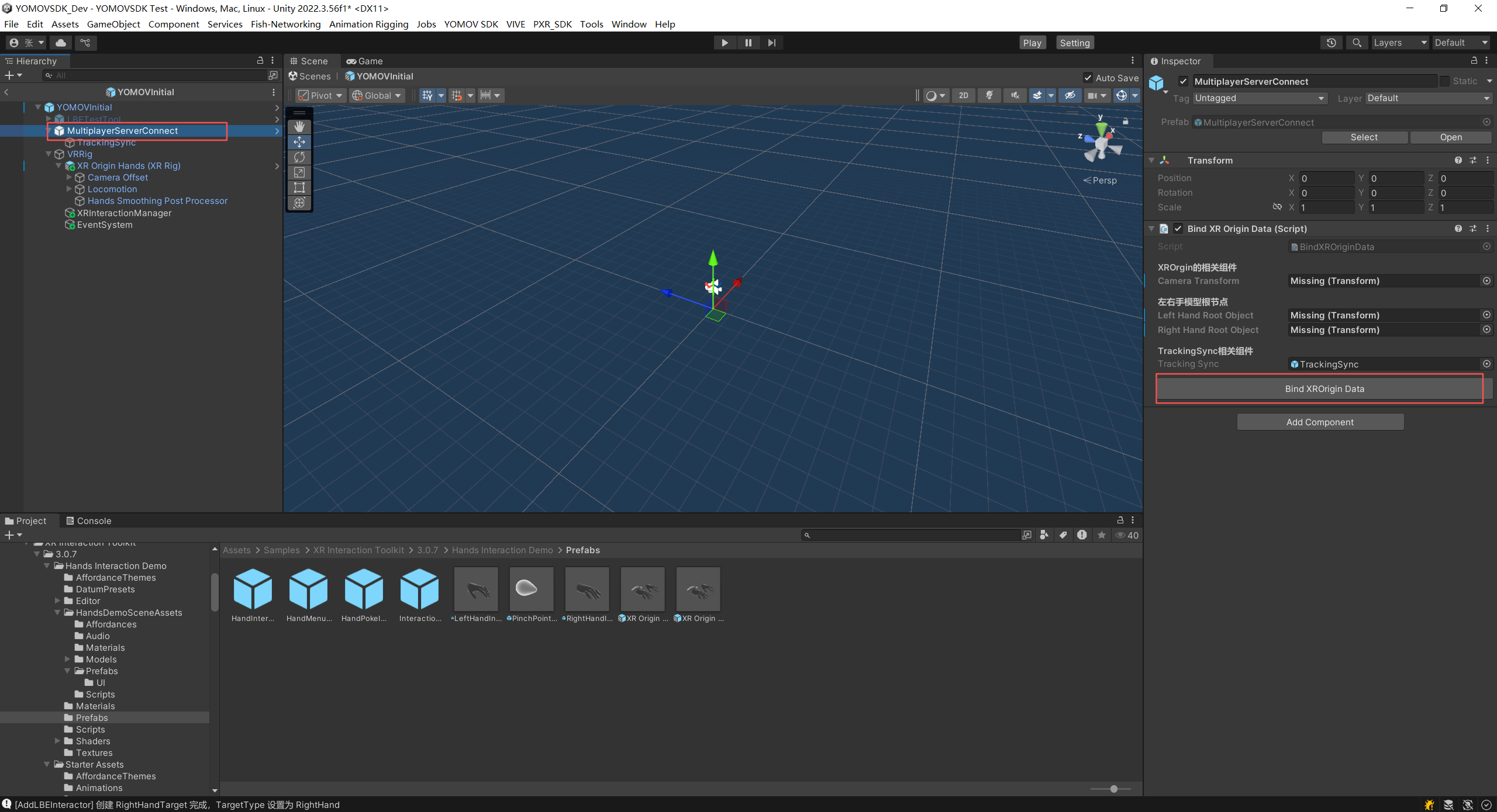
Bind XROrigin Data action
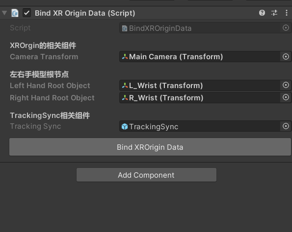
XR Origin data bound successfully
-
YOMOVInitial component reference:
GameObjects | Components | Added By | ||||
|---|---|---|---|---|---|---|
YOMOVInitial
|
| Automatically added | ||||
MultiplayerServerConnect
|
| Automatically added | ||||
LBETestTool
|
| Automatically added | ||||
MenuList | Automatically added | |||||
HandMenuWristButton |
| Automatically added | ||||
SceneSelectManager |
| Automatically added | ||||
TimelineSpeedManager |
| Automatically added | ||||
VRRig |
| Automatically added | ||||
XRInteractionManager |
| Manually added with one click | ||||
EventSystem |
| Manually added with one click | ||||
XROrigin | Created by the developer | |||||
MainCamera | ||||||
HeadTarget |
| Manually added with one click | ||||
Collider |
| Manually added with one click | ||||
EyeBlink |
| Manually added with one click | ||||
Left Controller | ||||||
LeftHandTarget |
| Manually added with one click | ||||
Right Controller | ||||||
RightHandTarget |
| Manually added with one click | ||||
Step 2: Create a Dynamic LBE Path
For a Free-Roam Experience, use a Dynamic Path whenever possible. Dynamic Paths can be adapted more precisely to different venue maps. Configuring and managing the LBE path is one of the most important parts of SDK integration. Divide the content into appropriate path units, then define the logic and sequence used to switch between them. This is the primary development and debugging work for path integration. For guidance on dividing an LBE path, see LBE VR Best Practices.
Select a Path Type
-
Open YOMOV SDK > Setting > LBEPath.
-
Under LBEPath Type, select Sequence to use a Dynamic Path.
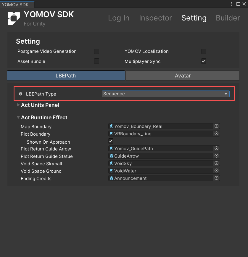
-
Create ActBuilder
-
From the YOMOV SDK menu, select Create ActBuilder to add an ActBuilder GameObject to the scene.
- ActBuilder contains two child GameObjects, Act and Plot. You will use them to create the LBE path.
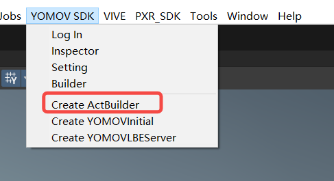
Create ActBuilder menu item
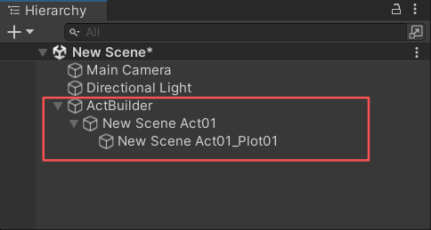
ActBuilder and its child GameObjects
Configure Plot Parameters
A Plot is a content unit in the LBE path system. It defines the content area currently available to the player; leaving this area moves the player into the Void Space. Multiple Plot content units make up an Act path unit. For details, see Product Overview > Plot.
-
Set the Plot type
-
Select the Plot Boundary component on the Plot GameObject and locate Plot Type.
-
If the player experiences the content by walking, set Plot Type to Walking.
-
If the player experiences the content while riding a moving vehicle, set Plot Type to Vehicle.
-
Under Related Vehicle, assign the corresponding vehicle GameObject. At runtime, the Plot boundary follows the vehicle and remains aligned with the LBE coordinate system.
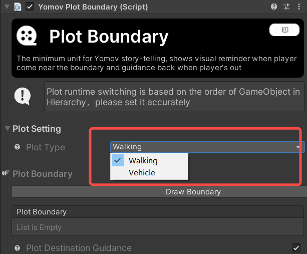
Content unit type: Walking
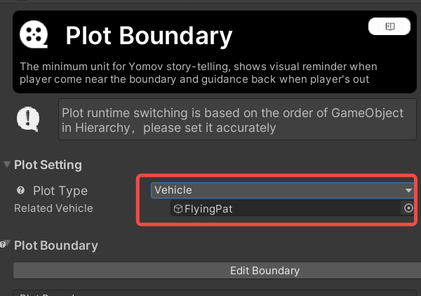
Content unit type: Vehicle
-
-
-
Draw the Plot boundary
-
Click Draw Boundary to enter boundary drawing mode.
-
Click points in sequence in the Scene view, then connect the final point to the first point to close the shape. The tool uses mesh-plane detection to locate each vertex and applies the height of the first vertex to subsequent points, producing a planar polygon.
-
If the Plot boundary is not visible, make sure Gizmos is enabled in the upper-right corner of the Scene view.
-
-
Click Quit Drawing, or press Esc twice, to leave drawing mode.
-
Click Edit Drawing to edit the Plot boundary.
-
Move the pointer near a vertex to display the transform gizmo, then drag the vertex to adjust it.
-
Move the pointer near an edge to display the add-vertex control. Click it to add a movable vertex to the polygon.
-
To delete a vertex, use the delete control in the panel. Pressing Esc deletes the entire component.
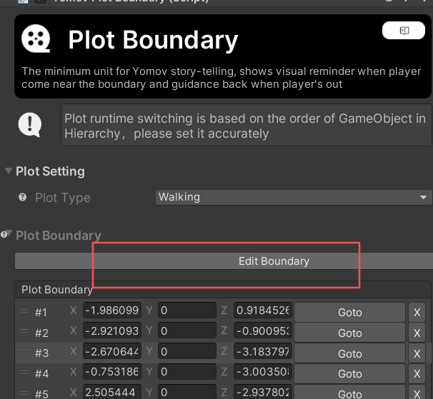
Edit the boundary
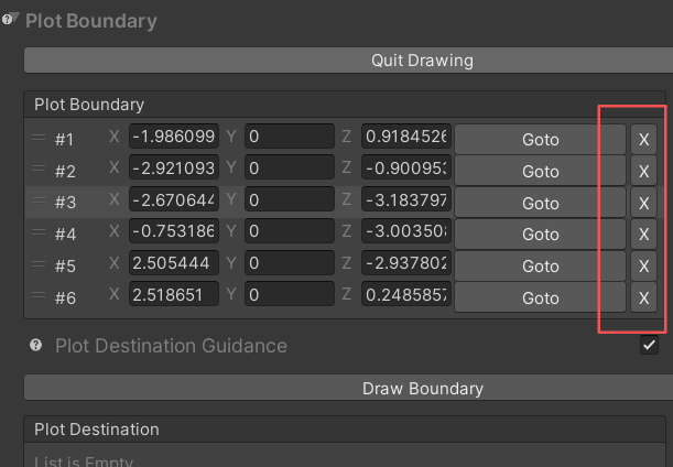
Delete a vertex
-
-
-
Configure player guidance (optional)
This feature shows players where to move to continue the experience, particularly when switching between content units. We generally recommend not using this feature. Whenever possible, guide players through character performances or interaction design built into the content, especially during unit transitions.
-
The workflow is similar to drawing a Plot boundary. Click Draw Boundary, draw the polygon vertices in the Scene view, and connect the final point to the first point. Click Quit Drawing when finished.
- The guidance area must be drawn inside the Plot boundary. Otherwise, the Inspector reports an error.
-
Under Display Timing, set when the guidance area appears. Timing begins when the Plot unit becomes active.
-
-
Create multiple Plot units
-
An Act can contain multiple Plots. In the Act Unit component, click Create Plot. Configure each Plot as described above.
-
When an Act contains multiple Plots, all Plot planes must use the same height. Otherwise, the Inspector reports an error.
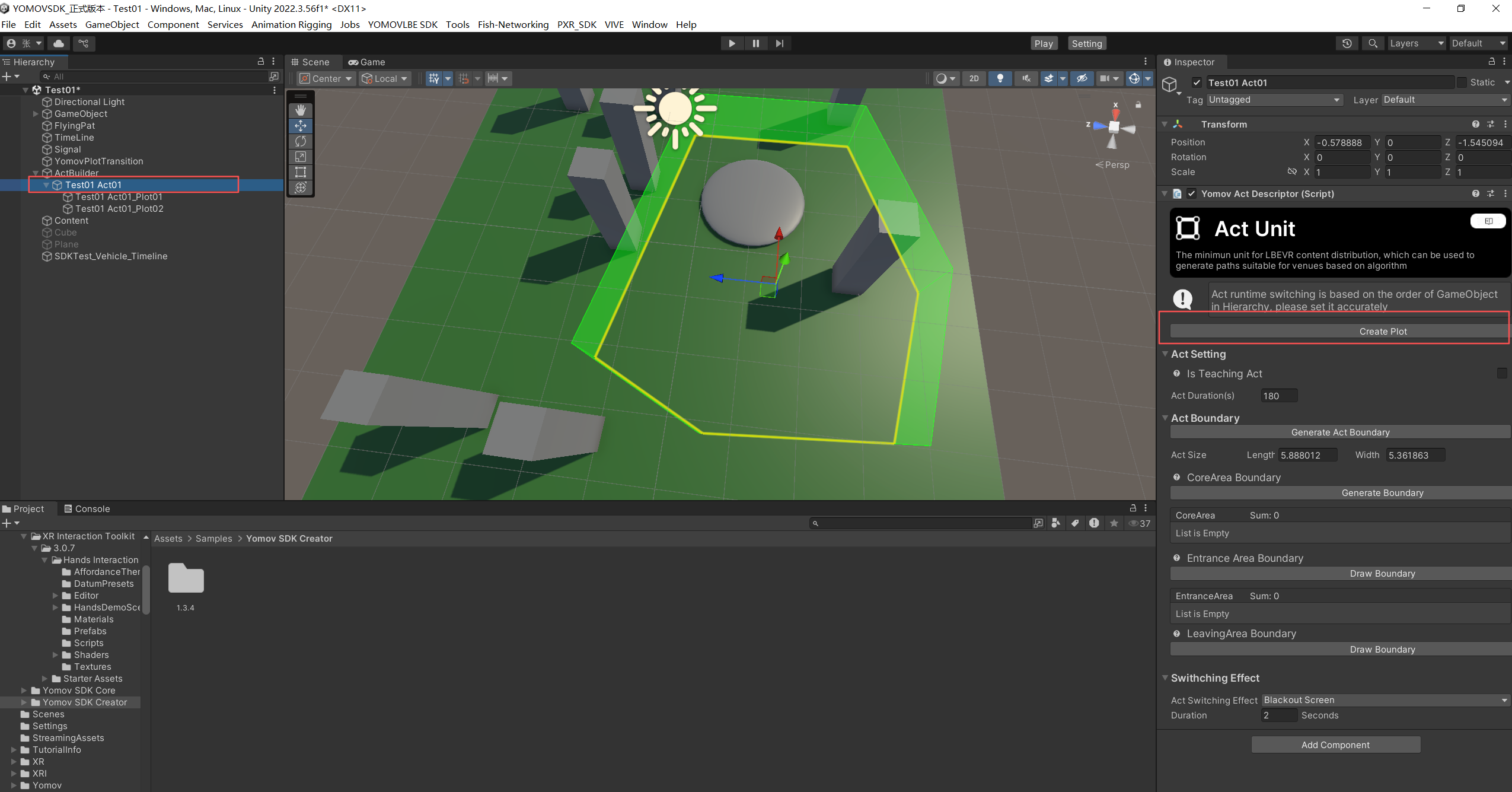
-
-
Connect multiple Plot positions
-
Multiple Plots in one Act represent a continuous physical-space experience. Adjacent Plots must overlap so the experience is not interrupted. If two Plots do not overlap, the Inspector reports an error.
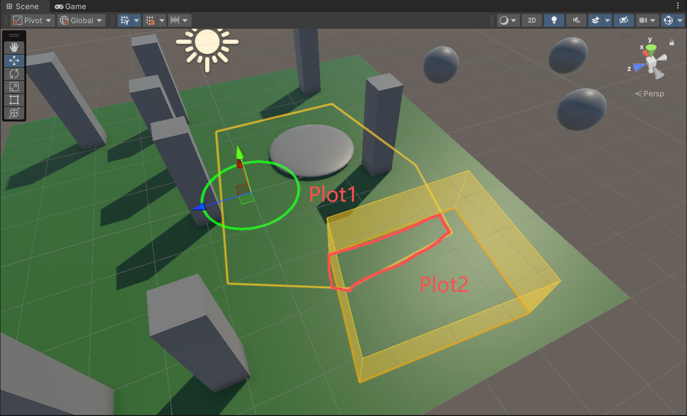
Correct: adjacent Plots overlap
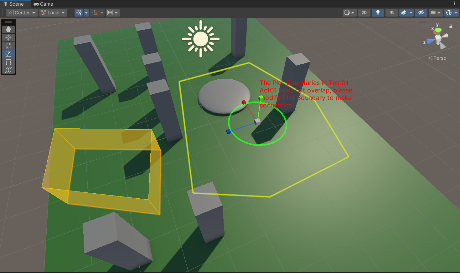
Incorrect: adjacent Plots do not overlap
-
-
For additional guidance, see Plot Drawing Best Practices.
-
Configure Act Parameters
An Act boundary is the union of all Plot boundaries in the Act. It is generated from the Plot boundaries and cannot be resized directly. An Act path unit is the smallest unit used for LBE VR distribution adaptation. A Plot content unit is the smallest content-experience area and defines the Void Space boundary. For details, see Act Concepts.
-
Generate the Act boundary automatically
-
After you draw the Plots, the SDK automatically generates the Act boundary from the union of all Plot boundaries in the Act. The green outline in the image below is the generated Act boundary.
-
If either dimension of an Act path unit exceeds 10 x 7 m, the Inspector warns that the unit may be too large for efficient venue distribution. The SDK does not prevent you from drawing it.
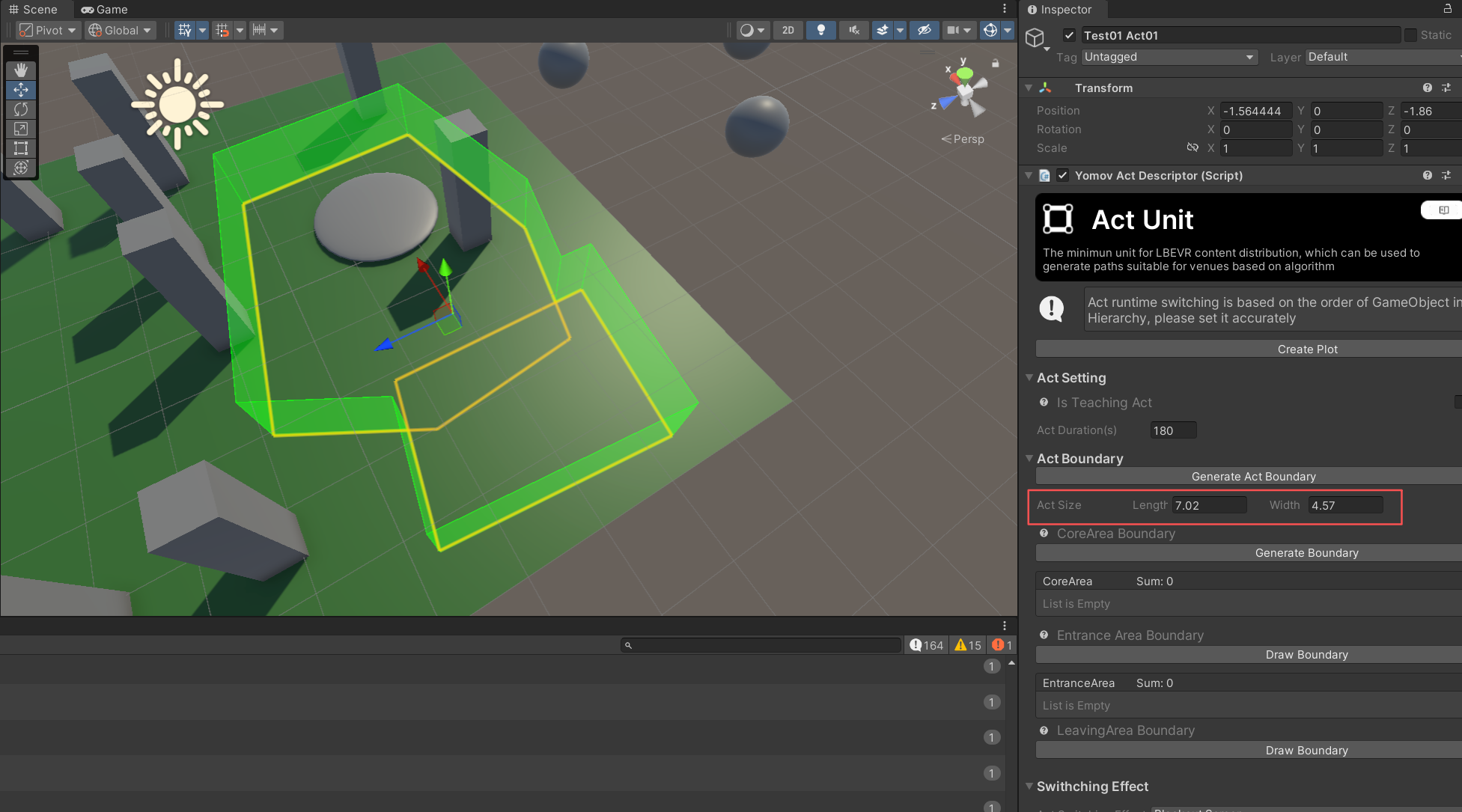
Within the 10 x 7 m range
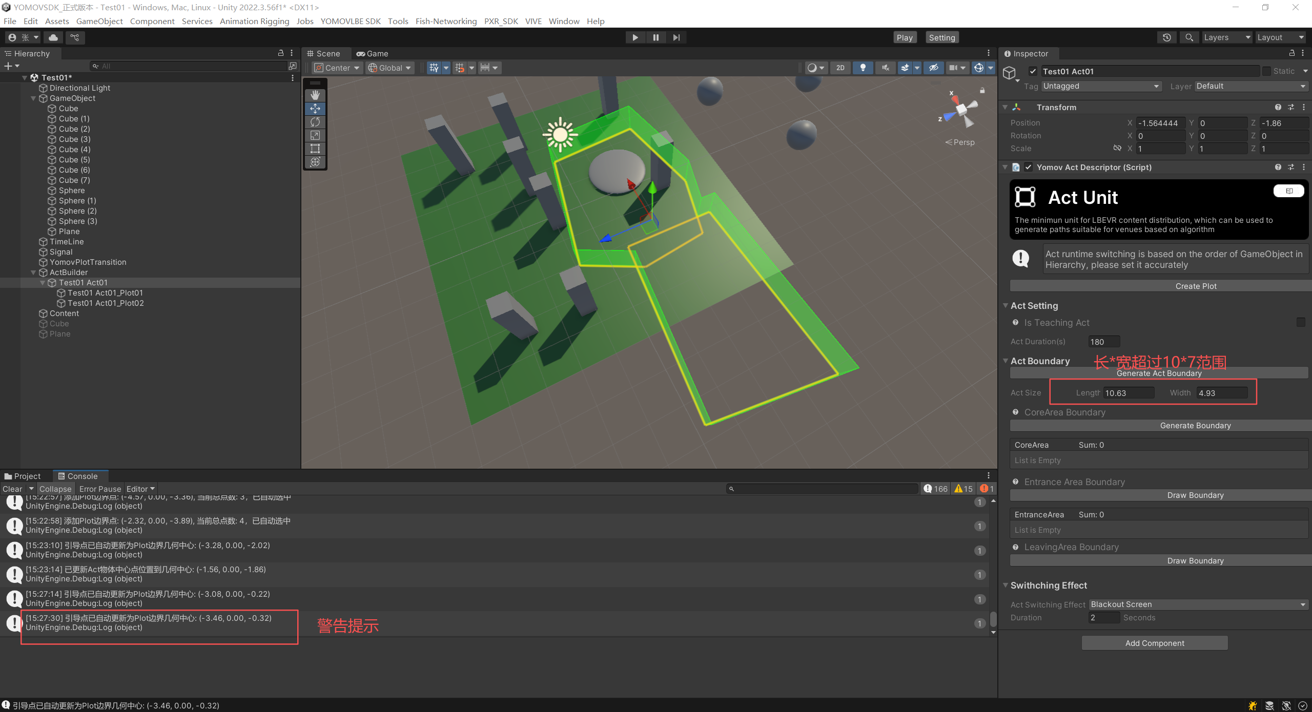
Length or width exceeds the 10 x 7 m range
-
-
Configure the core path-unit parameters
📌During LBE VR distribution, discrete Act path units are connected end to end to create a continuous experience path adapted to each venue map. Configure an Entrance Area and Exit Area for each Act. The space-efficiency algorithm uses these areas as inputs when connecting path units. For details, see LBE Path Concepts.
In some layouts, part of an Act may extend beyond the usable venue boundary. Configure a Core Experience Area (CoreArea) to give the algorithm a higher-priority boundary, ensuring that the player's essential experience path remains unobstructed while optional exploration areas may be omitted.
-
Configure the Core Experience Area
-
After drawing the Plots, locate CoreArea Boundary on the Act and click Create Boundary. The SDK creates a default CoreArea boundary by applying a 2 m inward offset to the Act boundary.
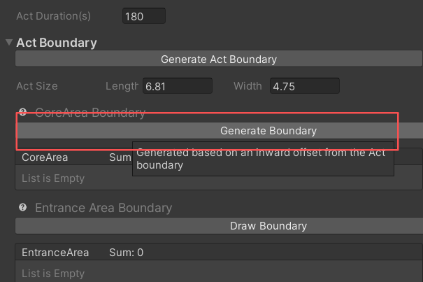
Create the CoreArea boundary
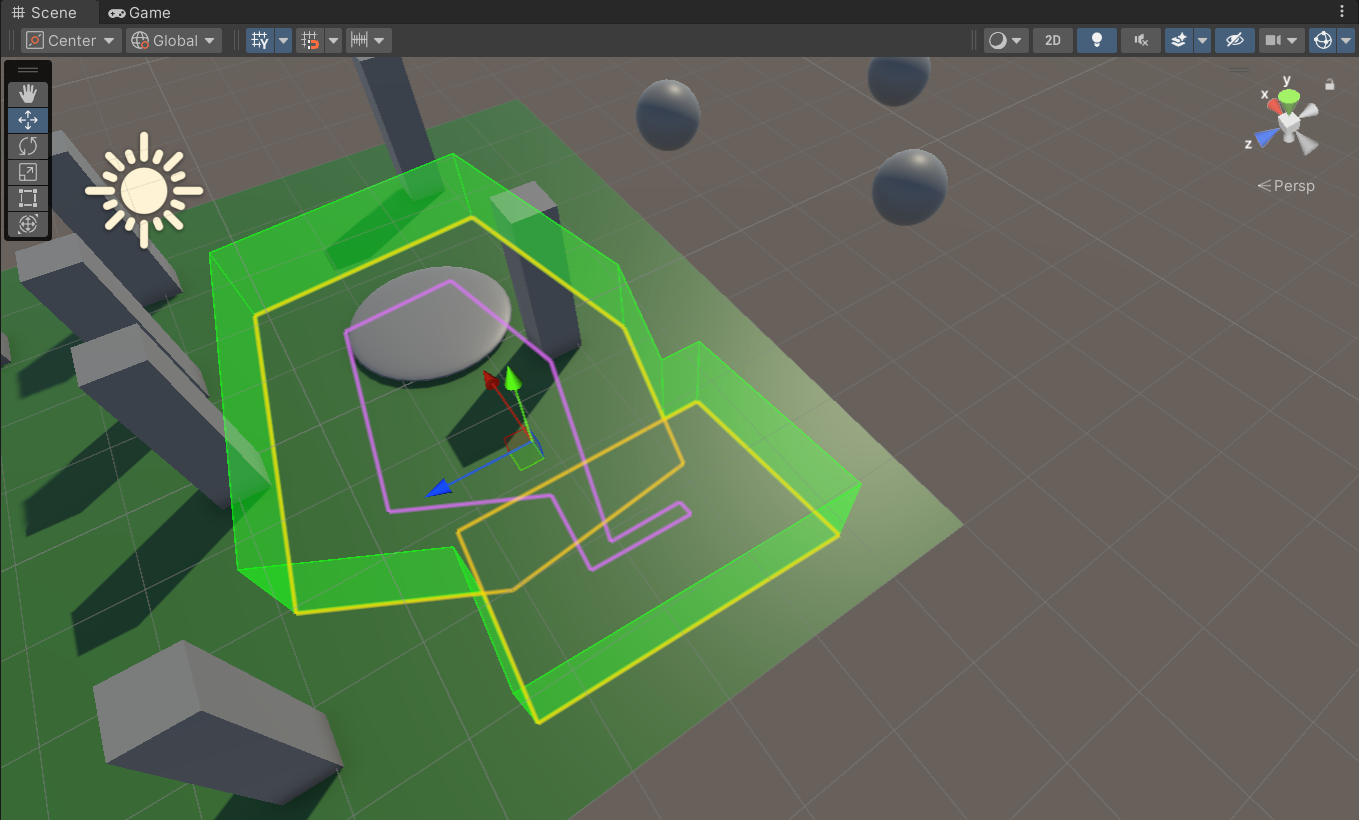
Automatically generated CoreArea boundary
-
If the automatically generated CoreArea boundary does not match the player's essential VR experience path, click Edit Boundary and adjust, add, or delete vertices in the same way as a Plot boundary.
-
-
Configure the Entrance Area
-
Under EntranceArea Boundary, click Draw Boundary.
-
Enter edit mode, click points in sequence in the Scene view, and connect the final point to the first point to close the polygon.
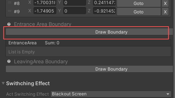
Draw Boundary action
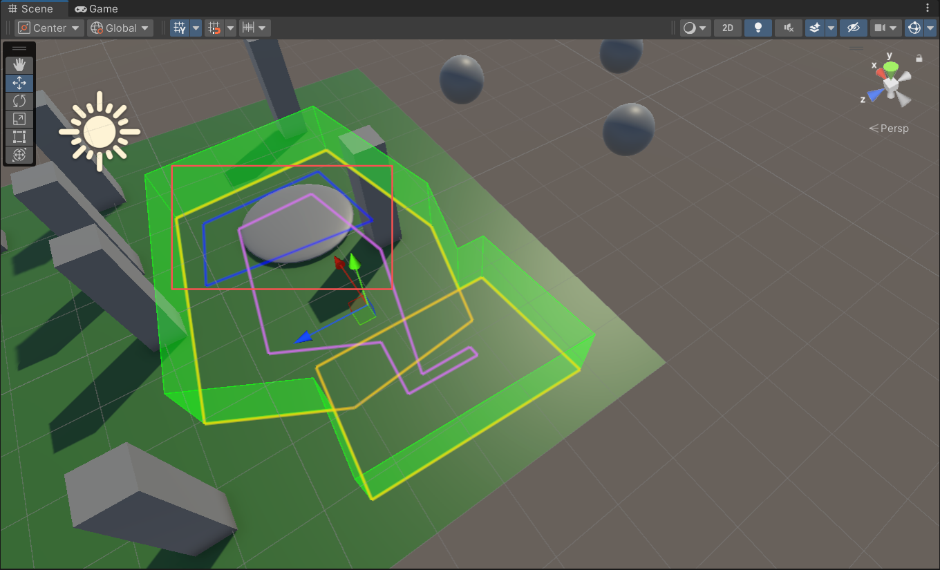
Entrance Area boundary
-
-
Configure the Exit Area
-
Under LeavingArea Boundary, click Draw Boundary.
-
In edit mode, click in the Scene view to create a circular Exit Area with a 2 m radius. Click Quit Editing to save and leave edit mode.
-
To adjust the Exit Area, enter edit mode and move its center. The default radius remains unchanged.
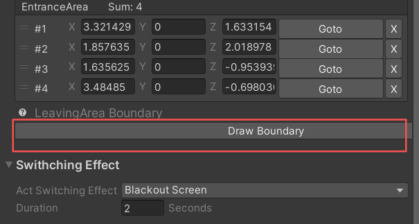
Draw Boundary action
-
-
-
Add a transition effect
-
Choose one of the following transition modes for the Act:
-
No transition
-
Black-screen transition + duration: Plays a fade-to-black transition when switching Acts (recommended).
-
White-screen transition + duration: Plays a two-second fade-to-white transition when switching Acts.
-
-
Set the transition duration. The default is 2 seconds and can be changed. This setting has no effect when no transition is selected.
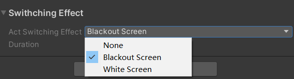
Transition effect
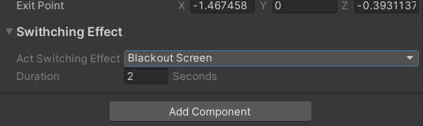
Transition duration
-
-
Create multiple Act units
-
A scene can contain multiple Acts. Select ActBuilder and click Create Act to create an Act with a Plot child GameObject.
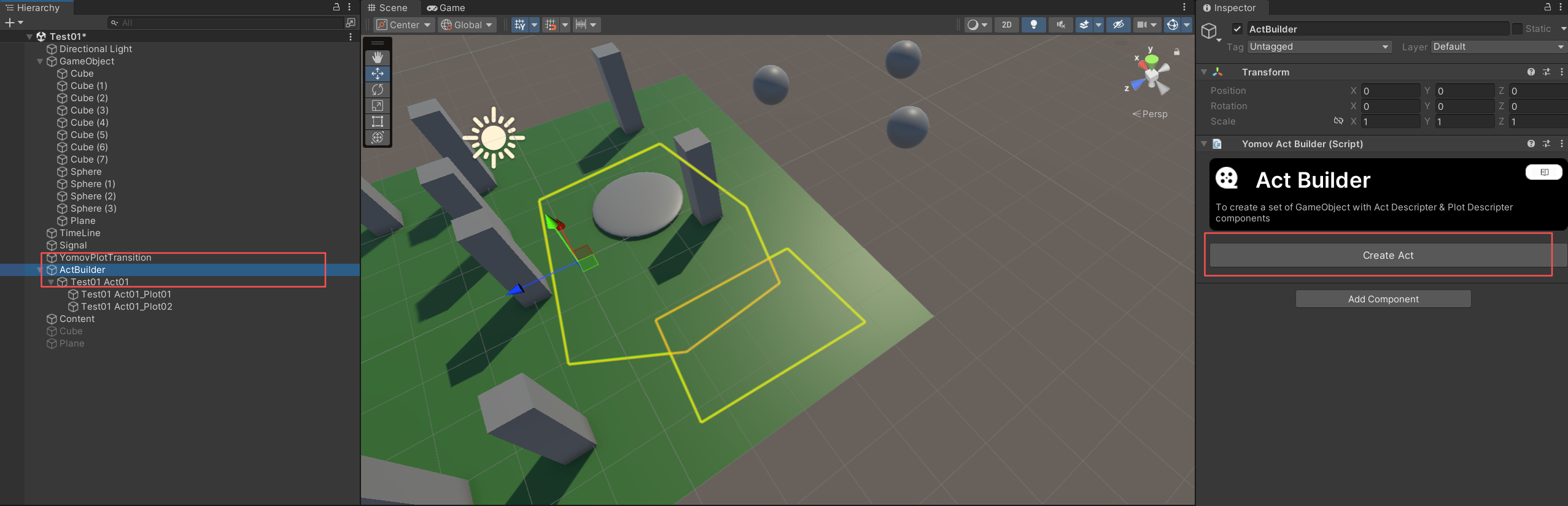
-
Recommendations for multiple Acts
At runtime, Acts in the same scene are adapted to the venue map. Players may perceive an in-place rotation or translation when switching Acts. Design the content together with an appropriate transition effect to keep the experience comfortable and coherent.
- For more information, see Act Drawing Best Practices.
-
Configure Path Switching
Configure path-switching logic and order after you have finished setting the path boundaries in every content scene. This substantially improves development efficiency. Path switching must be integrated with the corresponding content transition logic and triggered at the same time.
-
Call the path-switching method
-
First implement the content transition logic. The following example uses a Timeline Signal connected to a SignalReceiver.
-
Use Add Component to add the Plot Switch component to a GameObject in the scene.
-
Connect the GameObject containing Plot Switch to the SignalReceiver, then select the LoadNextPlot method.
-
Act switching is driven by Plot switching. Switching from the final Plot in an Act automatically advances to the next Act.
-
-
-
Configure the path-switching order
📌Important:
The final runtime sequence is generated from the scene order in Build Settings and the Act and Plot order in the Hierarchy. Click Update Act Sequence in the management panel to generate the path playback sequence.
-
Within each scene, arrange Act and Plot GameObjects from top to bottom in runtime order. Add all scenes containing path components to Build Settings and arrange those scenes from top to bottom in the same runtime order.
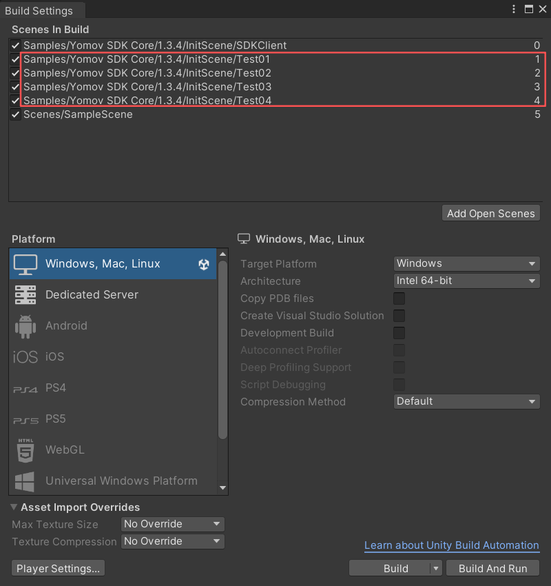
Build Settings: arrange scenes from top to bottom in runtime order
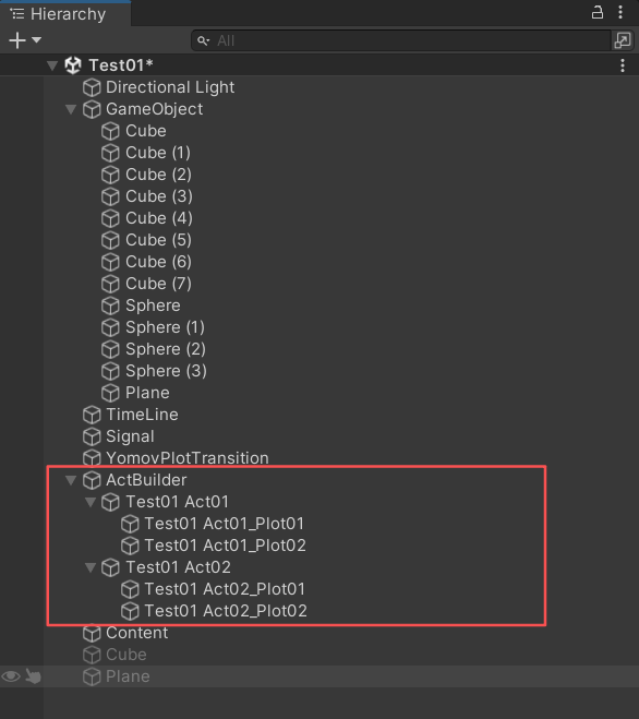
Hierarchy: arrange Acts and Plots from top to bottom in runtime order
-
Open YOMOV SDK > Setting > LBEPath and click Update Act Sequence. The SDK writes all Act and Plot sequence data to the Act Units Panel using the ordering rules above. This list defines the actual runtime sequence.
-
Whenever you add, remove, or reorder an Act or Plot, return to this panel and click Update Act Sequence again.
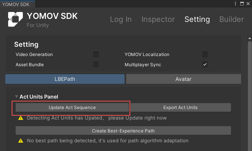
Update the path playback sequence
-
-
If an Act or Plot is missing required settings or contains invalid parameters, the management panel reports the issue. Resolve each error according to the displayed guidance.
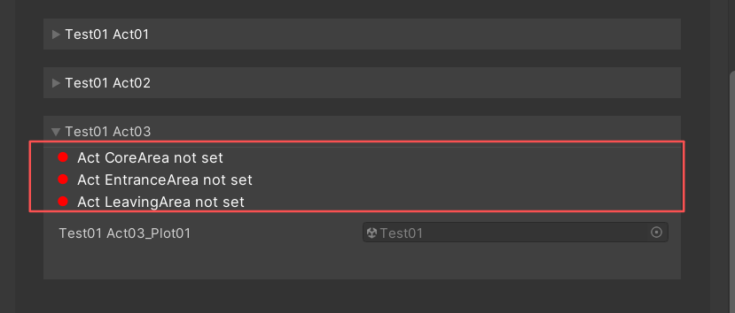
Path configuration errors
-
Configure Interaction Effects
The application loads YOMOV's standard LBE path interaction effects by default. Replace the assets in the configuration file to customize these effects for your content.
-
(Optional) Open YOMOV SDK > Setting > Act Setting > Act Runtime Effect and replace the required assets in the configuration.
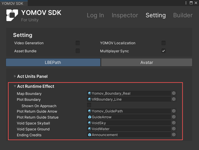
Path interaction effects configuration
-
Supported configuration entries
Configuration Key | Display Name | Asset Type | Preview |
|---|---|---|---|
Map Boundary | Map Boundary Effect | Texture | 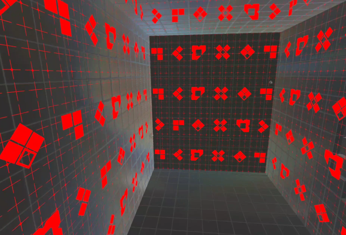 |
Plot Boundary | Content Boundary Effect | Texture | 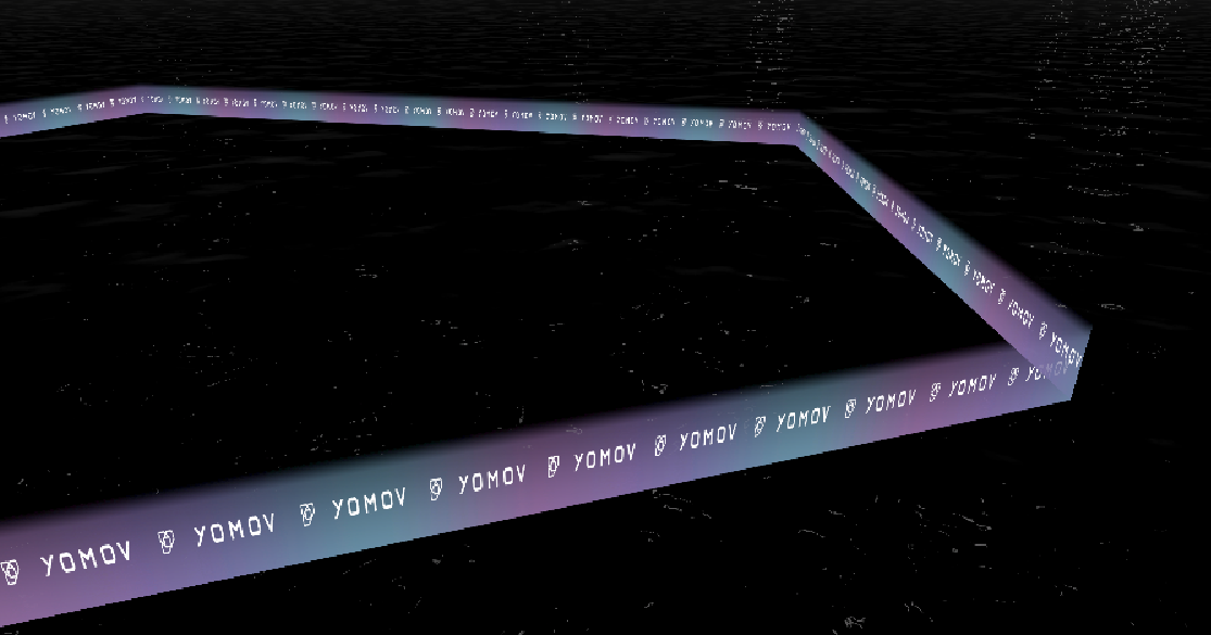 |
Shown On Approach | Show When Approached | On / Off | 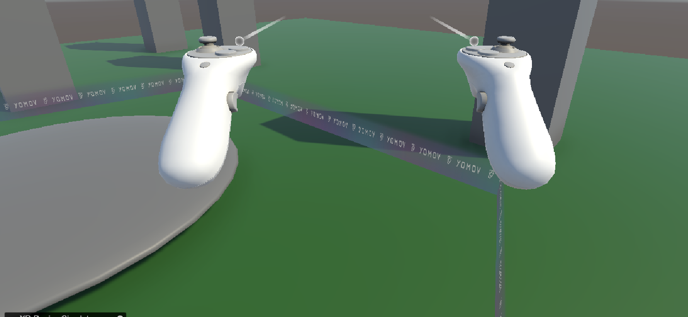
On: display the content boundary at 30% opacity when approached 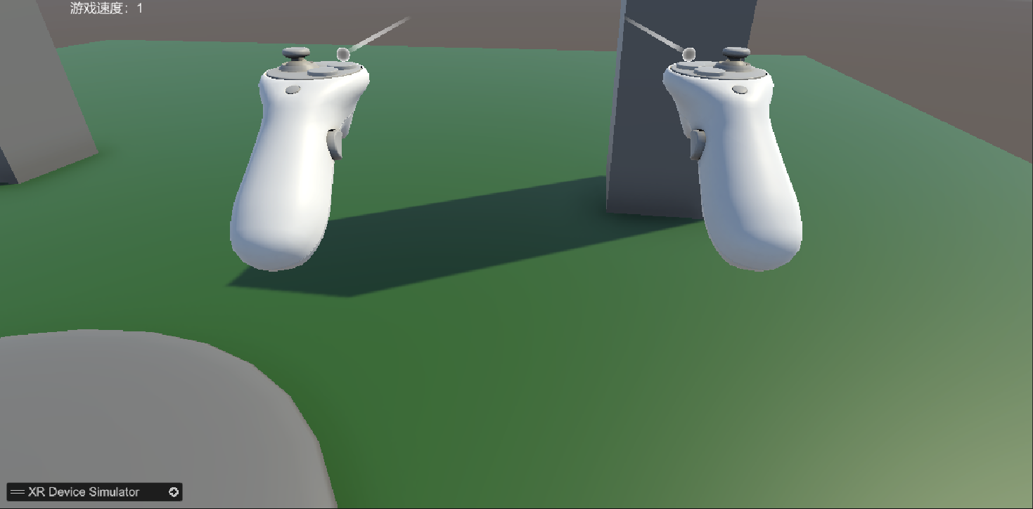
Off: do not display the content boundary when approached |
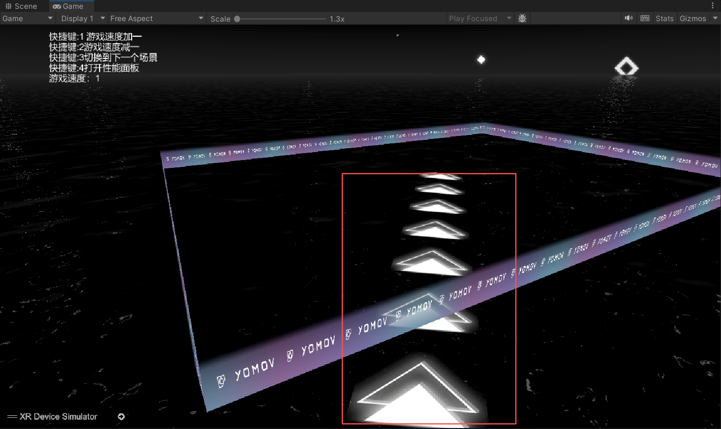
Plot Return Guide Arrow | Return-to-Content Guide Arrow | Texture | 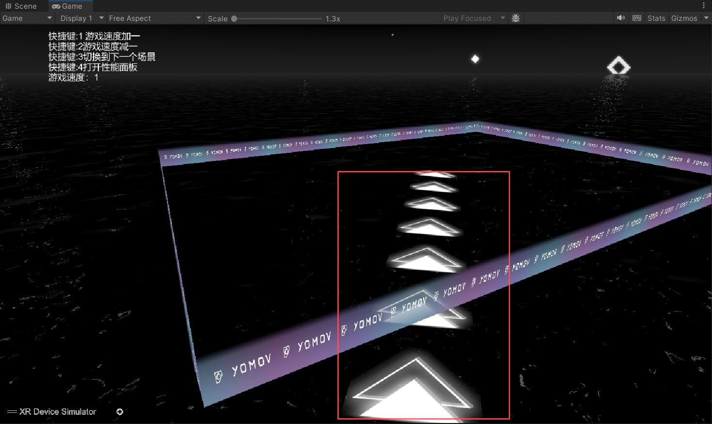 |
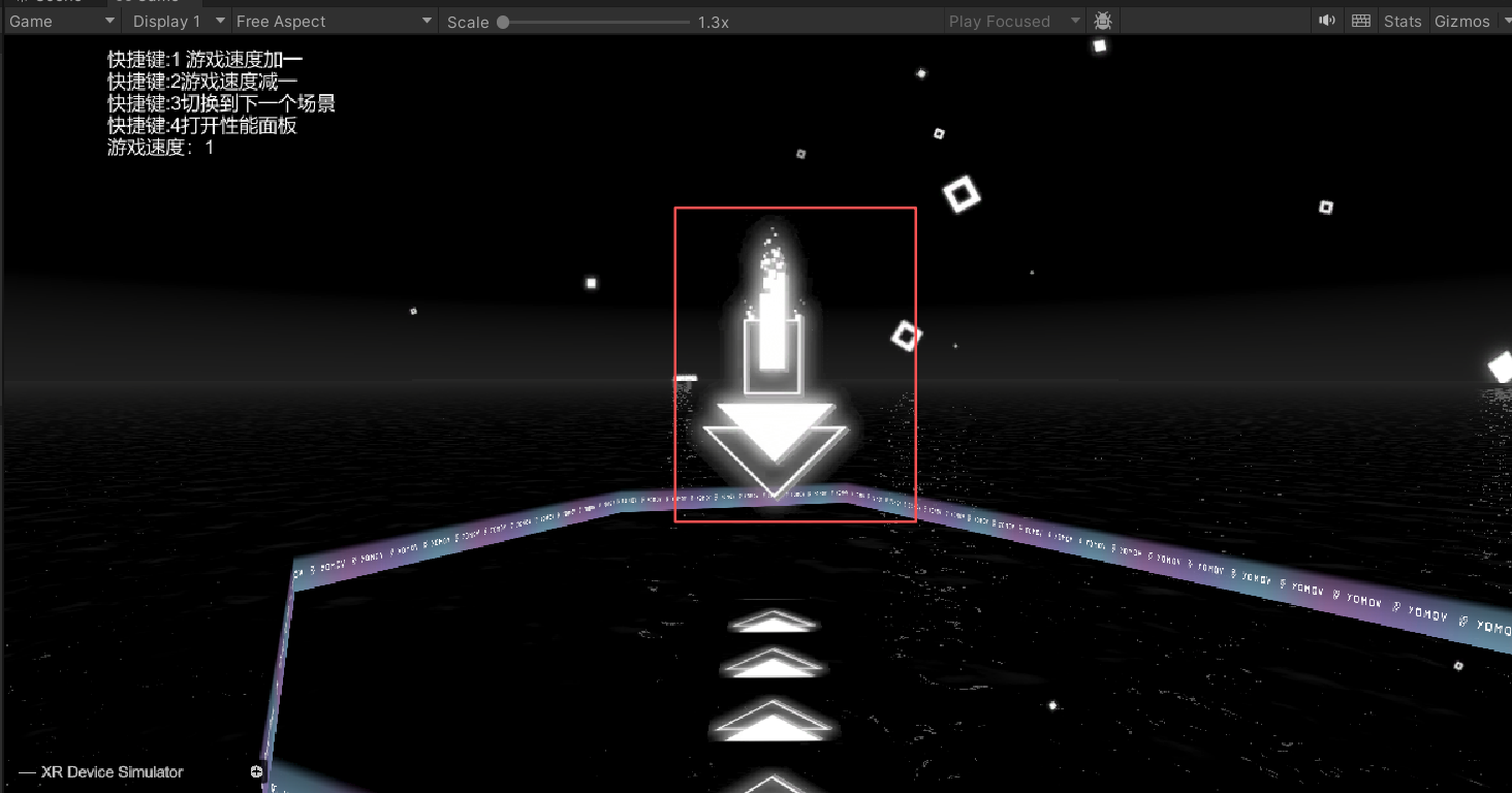
Plot Return Guide Statue | Return-to-Content Center Effect | Shader | 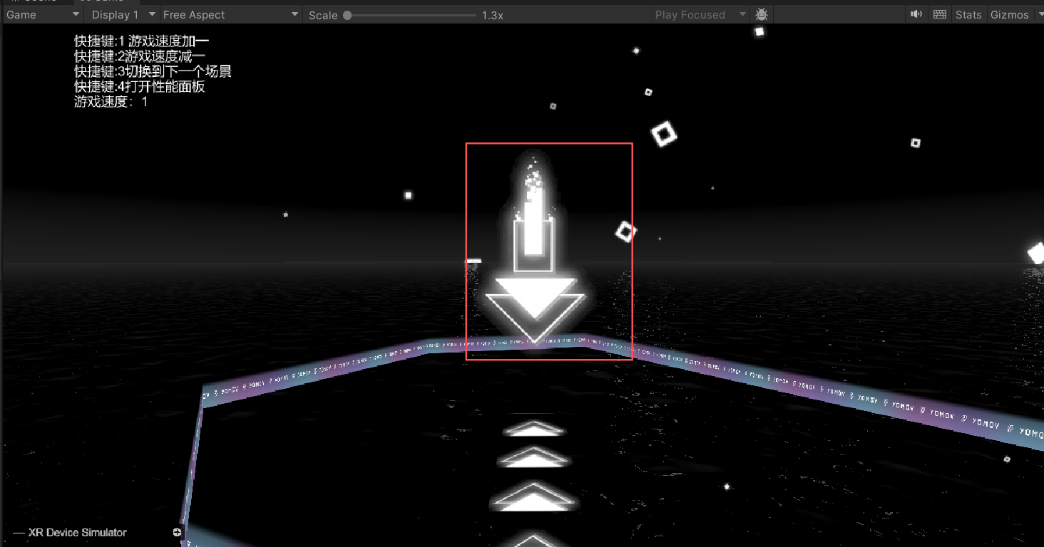 |
Void Space Skyball | Void Space Sky Sphere | Skybox | 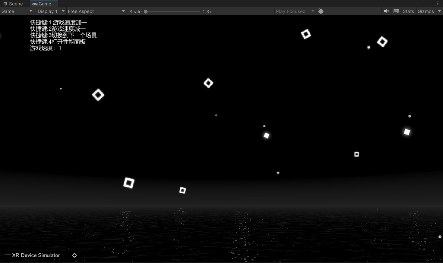 |
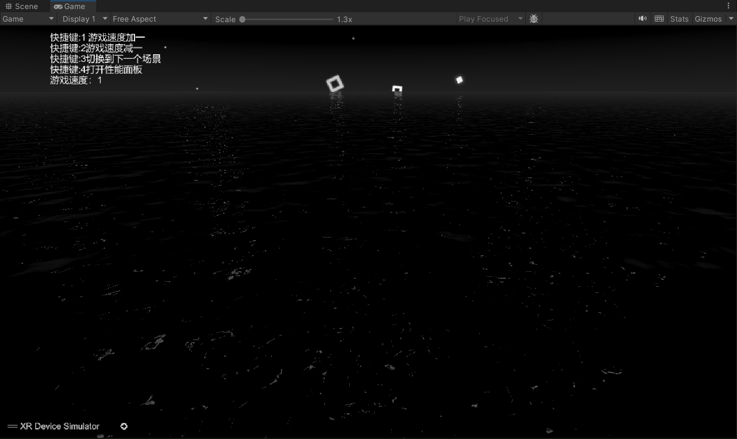
Void Space Ground | Void Space Ground Effect | Texture | 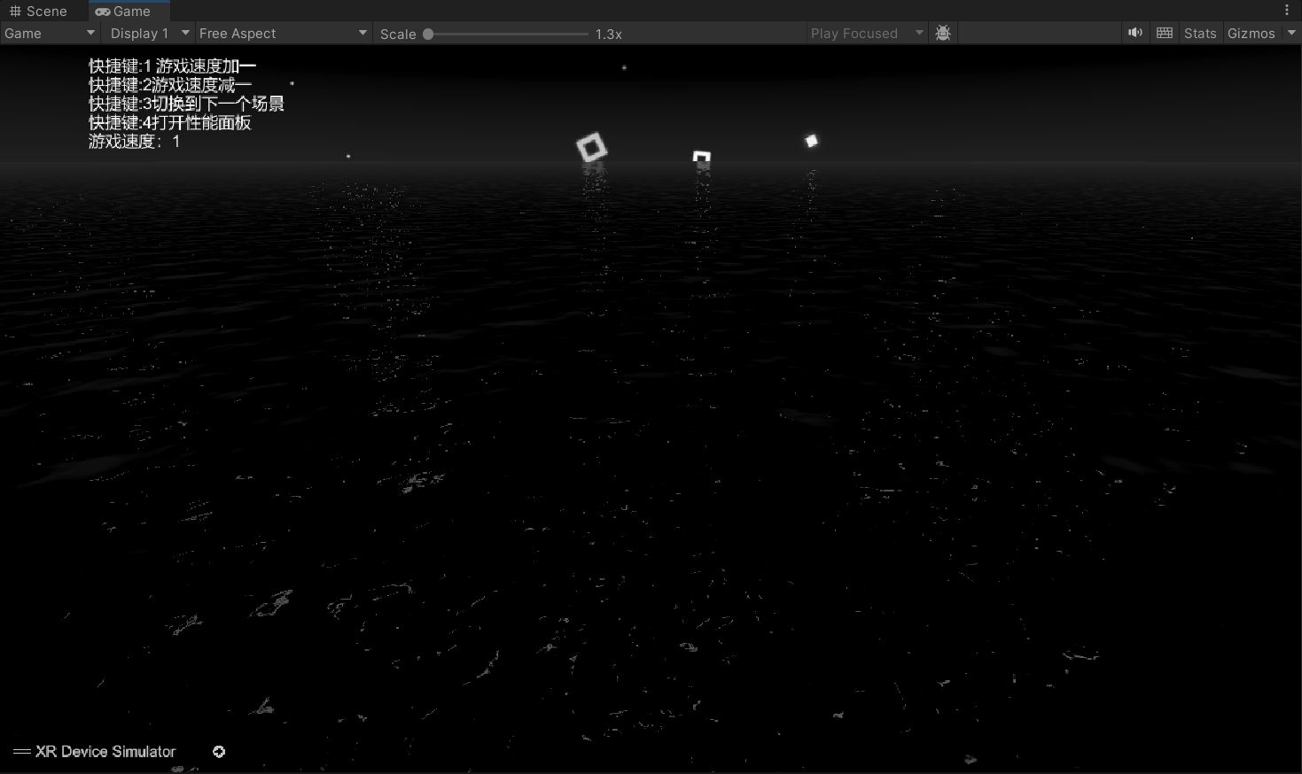 |
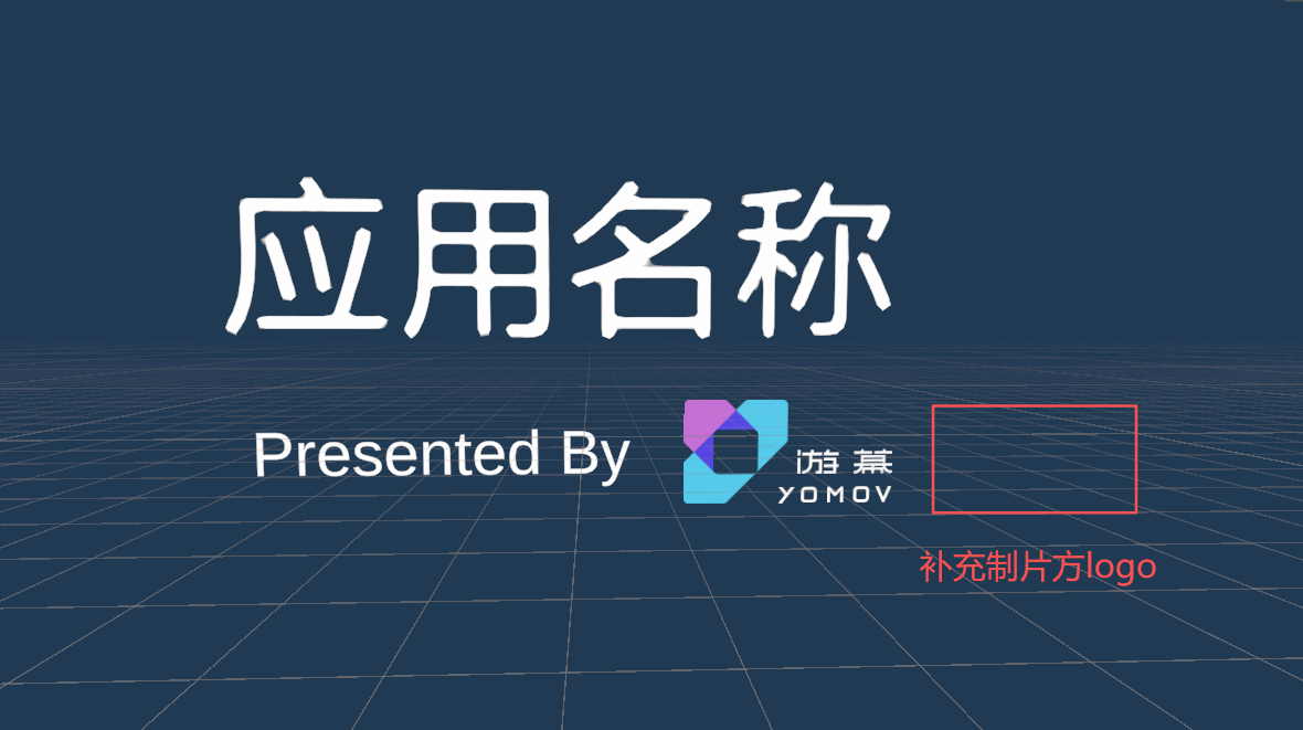
Ending Credits | Ending Credits | Text | 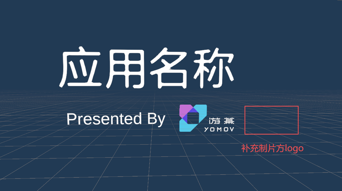 |
Run and Debug
After completing the configuration above, you can run and debug the content in the Unity Editor.
-
Start from any content scene
-
Open the scene you want to debug and click Play in the YOMOV SDK menu to run the content in LBE mode.
-
Important:
-
Do not use the standard Unity Editor Play button for this workflow. The SDK must first load the LBEPath capabilities from the initialization scene, so use the YOMOV SDK Play action.
-
Before starting, open YOMOV SDK > Setting > LBEPath and click Update Act Sequence to generate the playback sequence used at runtime.
-
-
-
Start from the initialization scene
-
Open the initialization scene and click the standard Unity Editor Play button.
-
Important:
-
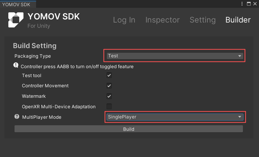
For testing, open YOMOV SDK > Builder, set Packaging Type to Test, and set MultiPlayer Mode to SinglePlayer. These settings start playback in single-player mode; otherwise, the application attempts to connect to the server.
-
Use the standard Unity Editor Play button rather than the YOMOV SDK Play action because the initialization scene already initializes LBEPath.
-
-
Step 2: Create a Fixed LBE Path
For a Small-Space Game, use a Fixed Path whenever possible. Fixed Paths provide precise physical separation between experiences during venue operation.
Select a Path Type
-
Open YOMOV SDK > Setting > LBEPath.
-
Under LBEPath Type, select Single to use a Fixed Path.
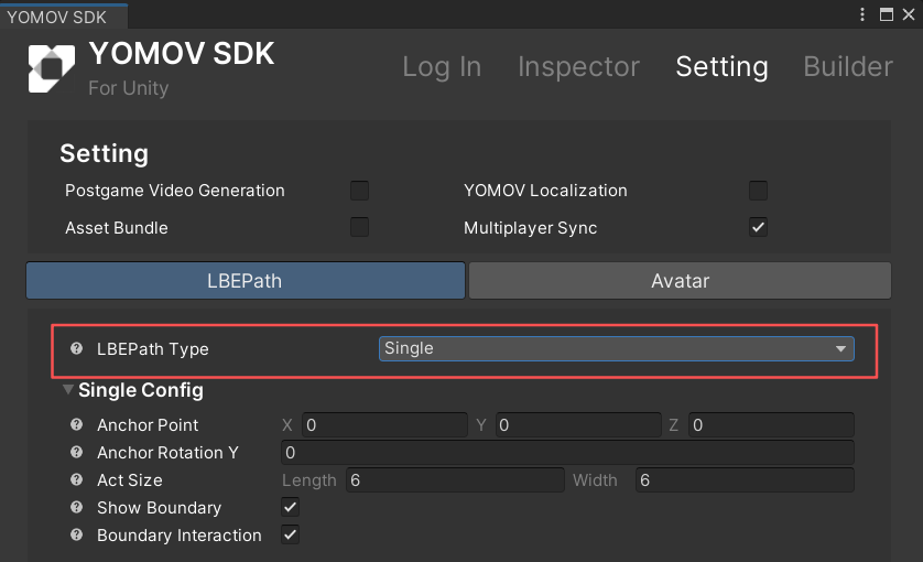
Select the LBE path type
-
Configure Global Path Parameters
-
Configure Fixed Path parameters
-
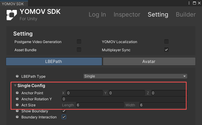
Open YOMOV SDK > Setting > LBEPath > Single Config.
-
Anchor Point: Set a Unity position (X, Y, Z) as the LBE origin for content playback. By default, this point is aligned with the positioning origin of the venue map.
- The default is (0, 0, 0), which aligns the Unity origin with the venue-map origin.
-
Anchor Rotation: Set the Y-axis rotation used as the LBE orientation for content playback. By default, this orientation is aligned with the venue-map orientation.
- The default is 0, which aligns the default Unity orientation with the venue-map orientation.
-
Act Size: Define the rectangular footprint required for the complete content experience. This is the combined playable footprint across all content scenes.
-
Enter this value in the application's backend configuration so the path server can use it for scheduling.
-
Length: Size along the Unity X axis
-
Width: Size along the Unity Y axis
-
-
-
Configure Fixed Path presentation effects
-
Open YOMOV SDK > Setting > LBEPath > Single Config.
-
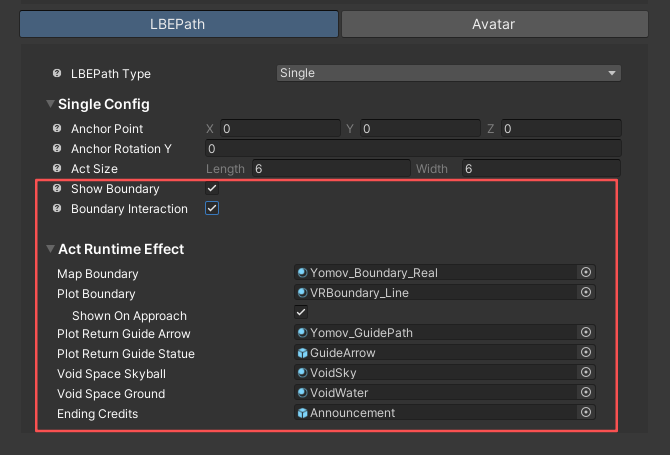
Boundary Interaction
-
When enabled, the content uses YOMOV's built-in boundary effects and interaction logic.
-
When disabled, the built-in YOMOV SDK boundary interaction is inactive. Disable it if your content already implements its own boundary behavior.
- Supported configuration entries
Configuration Key
Display Name
Asset Type
Preview
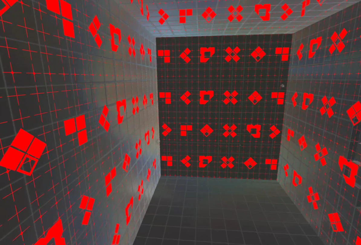
Map Boundary
Map Boundary Effect
Texture
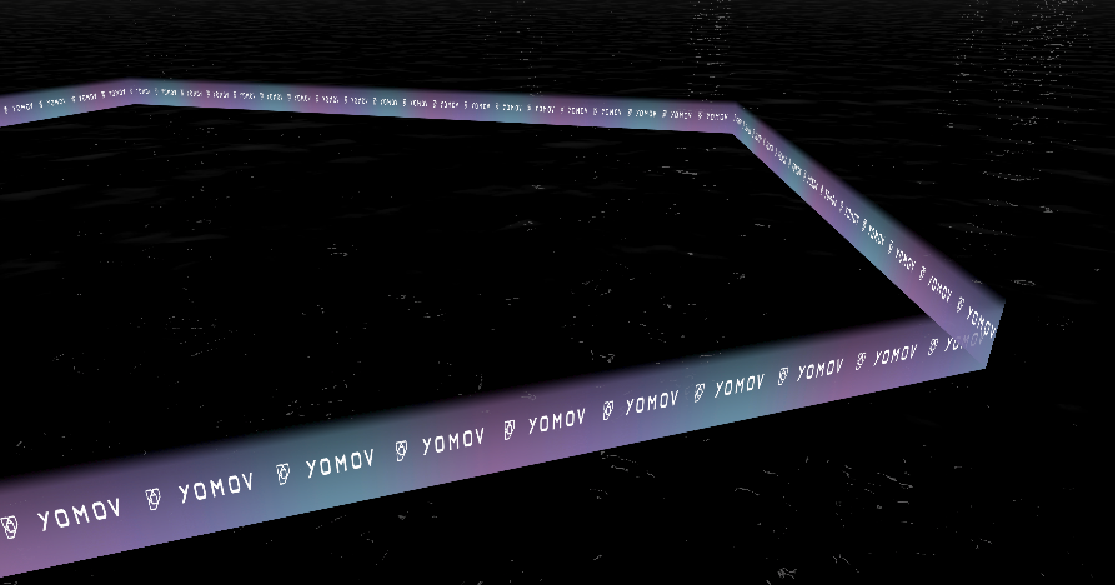
Plot Boundary
Content Boundary Effect
Texture
Shown On Approach
Show When Approached
On / Off
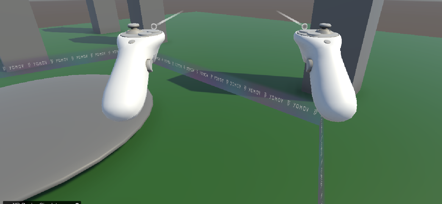
On: display the content boundary at 30% opacity when approached
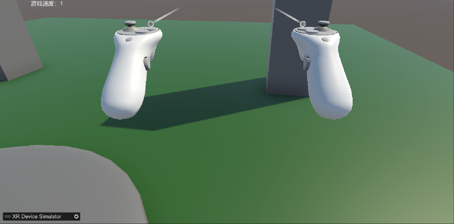
Off: do not display the content boundary when approached
Plot Return Guide Arrow
Return-to-Content Guide Arrow
Texture
Plot Return Guide Statue
Return-to-Content Center Effect
Shader
Void Space Skyball
Void Space Sky Sphere
Skybox
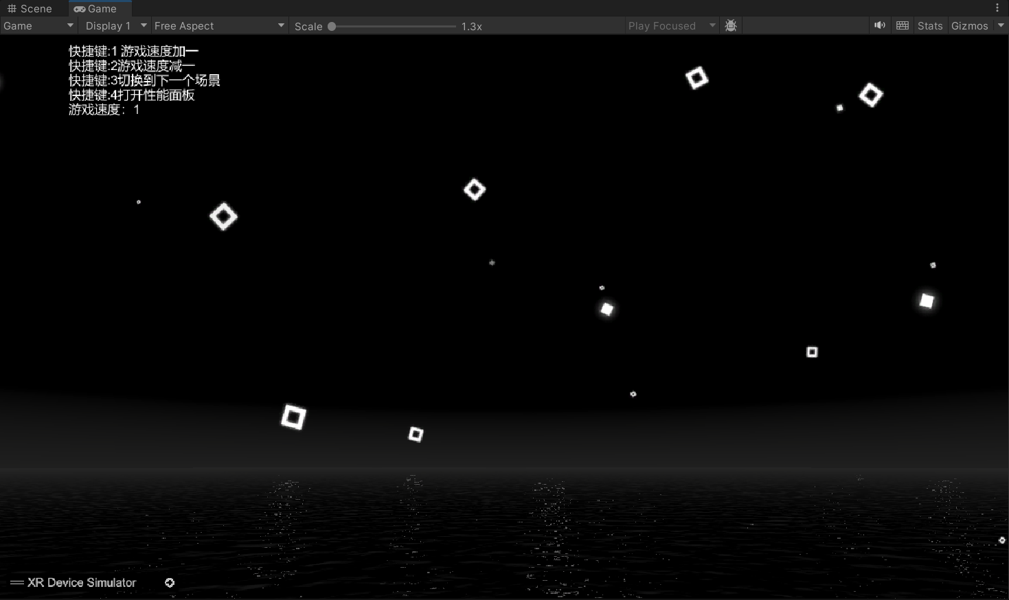
Void Space Ground
Void Space Ground Effect
Texture
Ending Credits
Ending Credits
Text
-
-
Adjust the Path Position in the Scene
-
From the YOMOV SDK menu, select Create ActBuilder to add an ActBuilder GameObject to the scene.
- ActBuilder contains two child GameObjects, Act and Plot, used to create the LBE path.
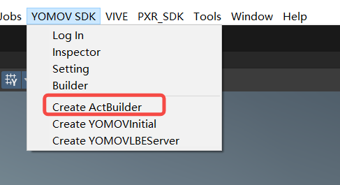
Create ActBuilder menu item
-
Select ActBuilder and click Create Single Act in the Inspector to create a Fixed Path unit.
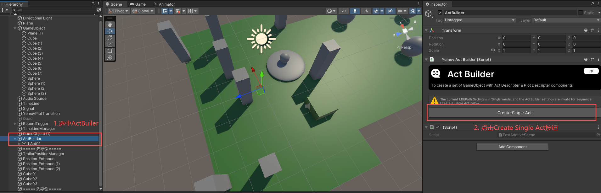
Create a Fixed Path unit
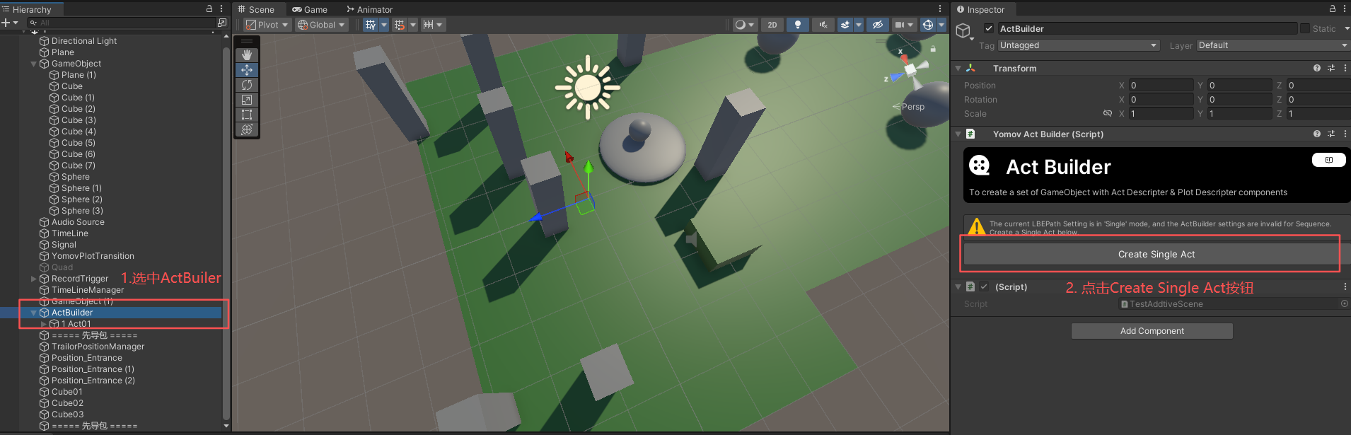
Fixed Path unit created
-
Path units in every scene inherit the globally configured size and are displayed visually in the Scene view.
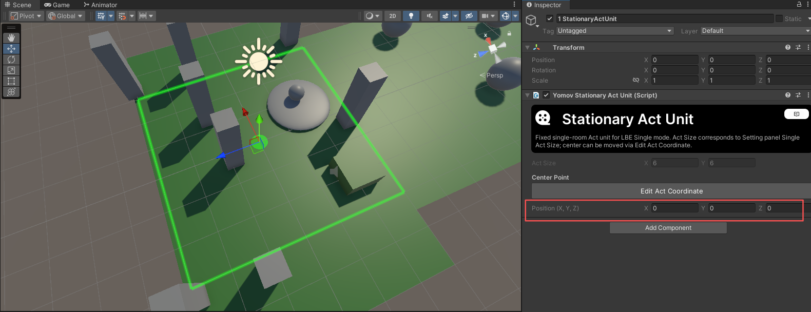
Fixed Path unit visualization
-
You can move or rotate a path unit in the scene, but you cannot resize it.
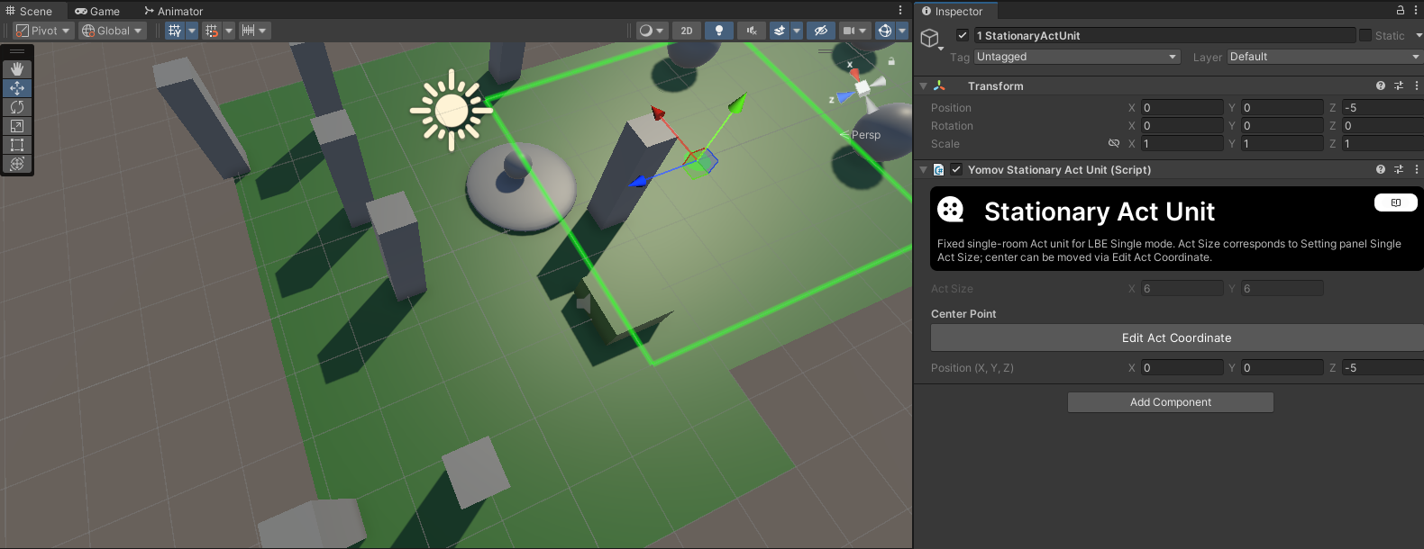
Move and rotate a Fixed Path unit
-
During venue scheduling, the Fixed Path anchor position and orientation in each scene are matched to the LBE position selected by the scheduling algorithm. The content is then played at that position on the venue map.
-
Usage guidance
-
Every scene uses the same footprint and loads at the Unity origin: Configure the global size only; no scene-level adjustment is required.
-
Scene footprints vary, but every scene loads at the Unity origin: Add a Single Act to each scene and verify that it contains the complete scene footprint.
-
Some scenes do not load at the Unity origin: Add a Single Act to each scene and adjust its position so the different scene locations align during scheduling.
-
Scenes do not load at the Unity origin, and the content already manages scene placement: Configure the global size only and make sure every loaded scene remains within that footprint.
-
-
Step 3: Configure Player Avatars
Player avatar configuration controls each player's appearance, group assignment, visibility, position, and animation in a multiplayer experience. Avatar models are connected to IK animation, hand interaction, multiplayer synchronization, and other systems. This is essential to a reliable LBE VR experience, but it is also one of the most time-consuming parts of integration and debugging. Follow these steps carefully to minimize later debugging work.
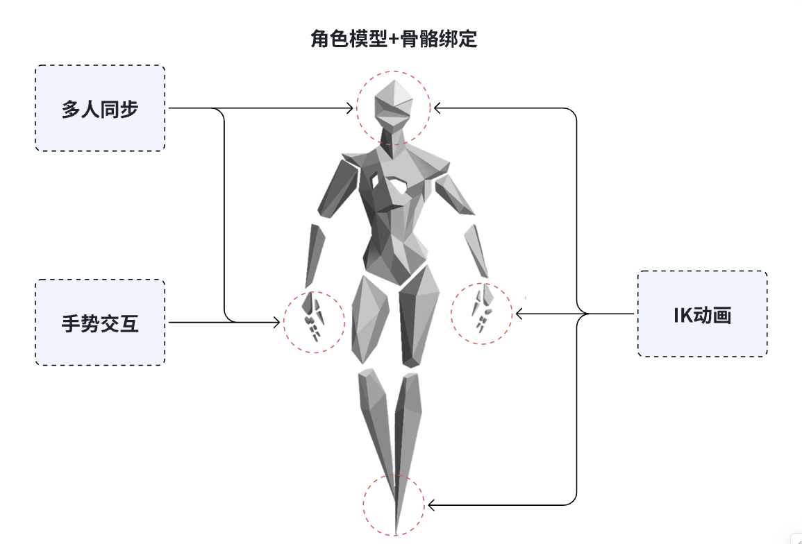
Team Player Avatars
Team Player: A player whose content playback starts as part of the same party during an on-site LBE VR session.
- Team Players can use different selected avatar appearances. Their avatars are visible across the full venue map.
Non-Team Player: A player whose playback does not start as part of the same party.
- Non-Team Players, whether they are running the same or different content, use the same default avatar appearance and are displayed only when they are within 5 m of the local player.
-
Open YOMOV SDK > Setting > Avatar > Team Player Avatar and click the add button. The SDK creates and configures a Team Player avatar Prefab Variant.
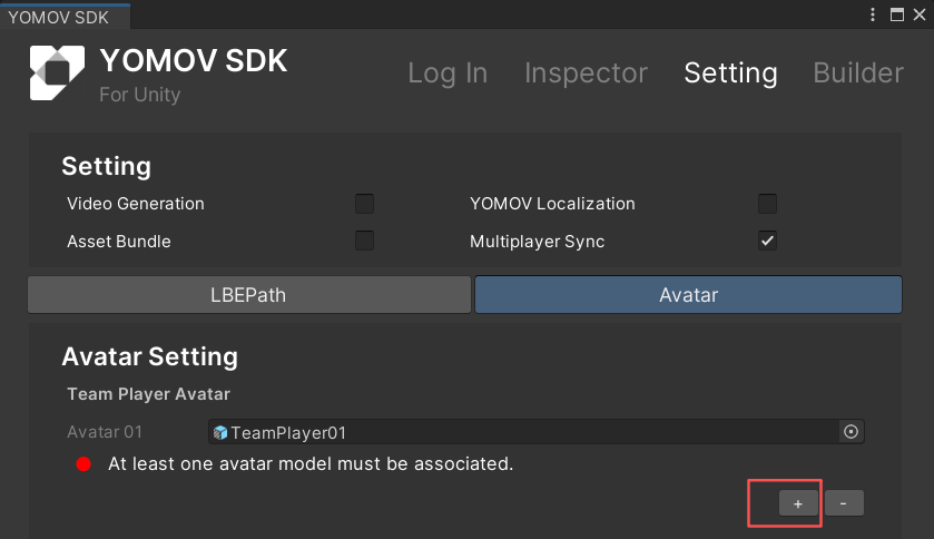
Avatar management: add an avatar
-
Bind your avatar model to the Prefab as follows:
-
Open the Team Player Prefab and drag your avatar model, configured with a standard Humanoid rig, into the Prefab.
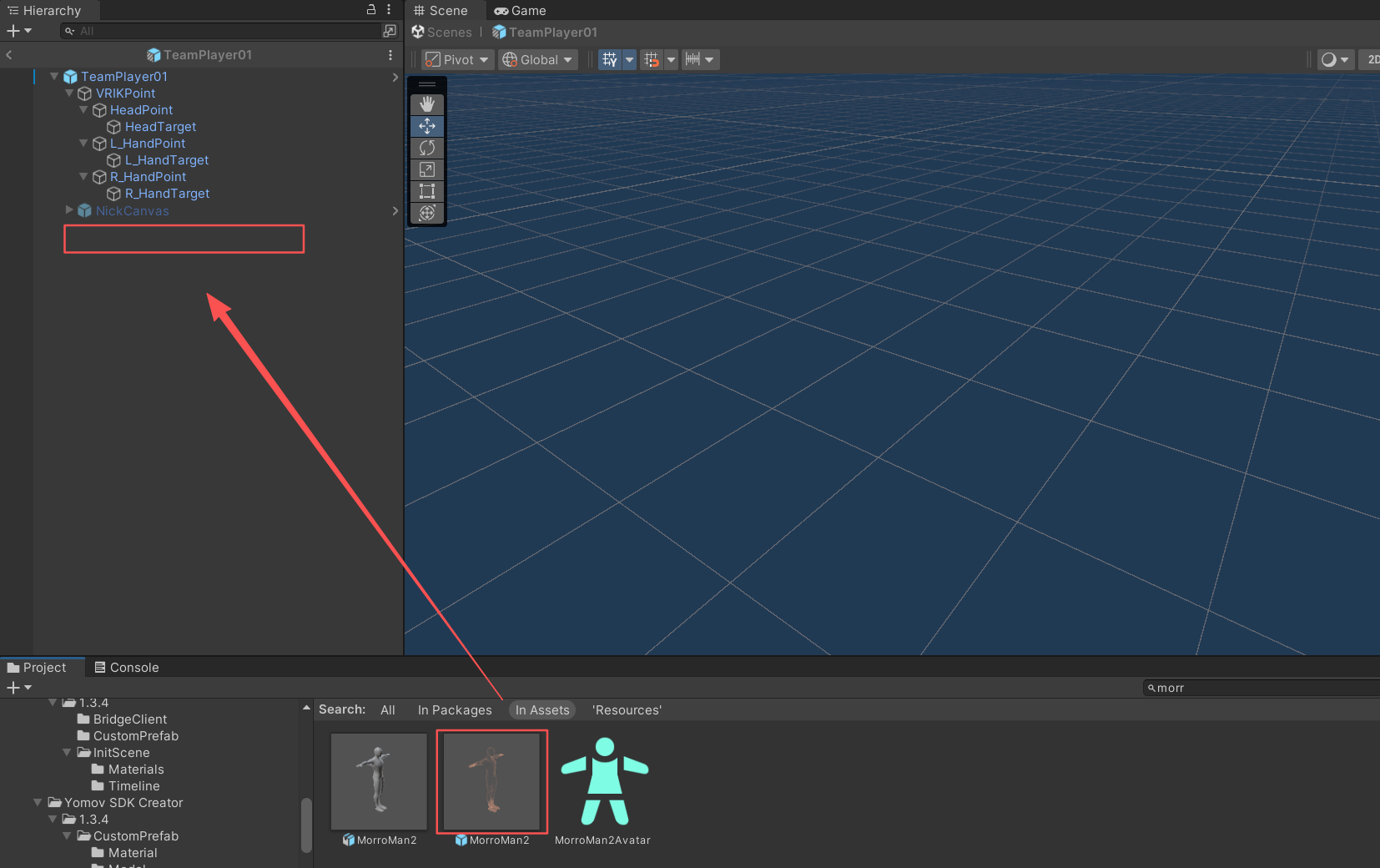
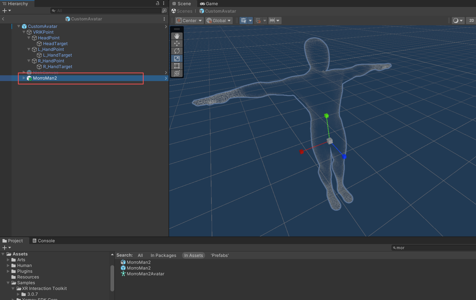
-
Select the parent TeamPlayer GameObject. In Custom Avatar Manager, assign the avatar model you just added.
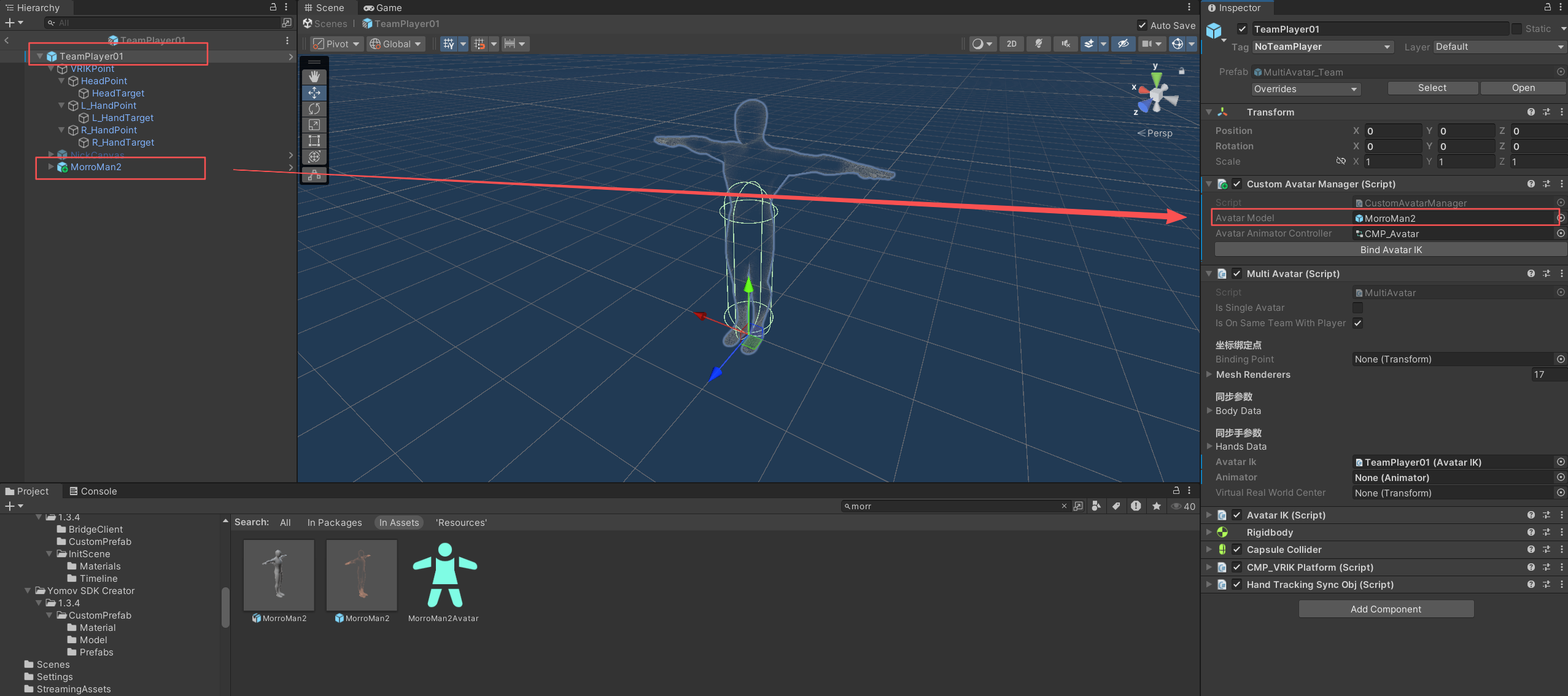
Assign the avatar model
-
Click Bind Avatar IK to bind the avatar's IK automatically.
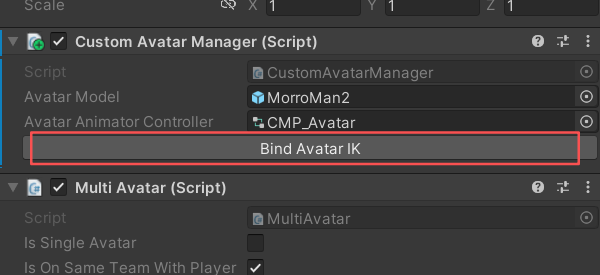
Bind Avatar IK
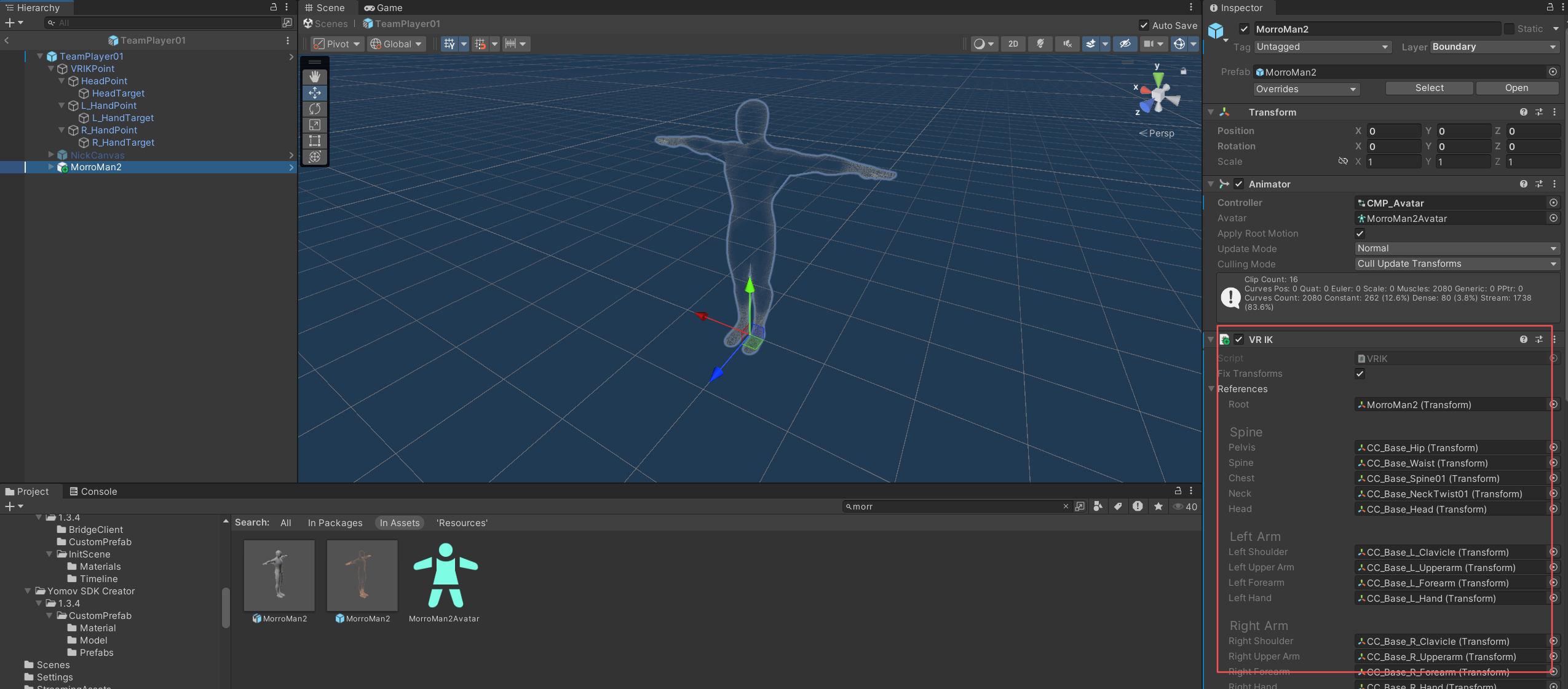
Avatar IK bound successfully
-
-
Create multiple Team Player avatar appearances
Some LBE VR experiences allow each player to choose a different avatar. Add and configure multiple avatar Prefabs; at playback start, the selected avatar configuration name in the startup parameters determines which model is instantiated.
-
Open YOMOV SDK > Setting > Avatar > Team Player Avatar and click the add-avatar button multiple times. The SDK creates and associates multiple avatar Prefabs. Replace the model in each Prefab as described above.
-
Each avatar Prefab must have a unique name so the selected avatar can be matched correctly. The SDK assigns distinct names when the Prefabs are created.
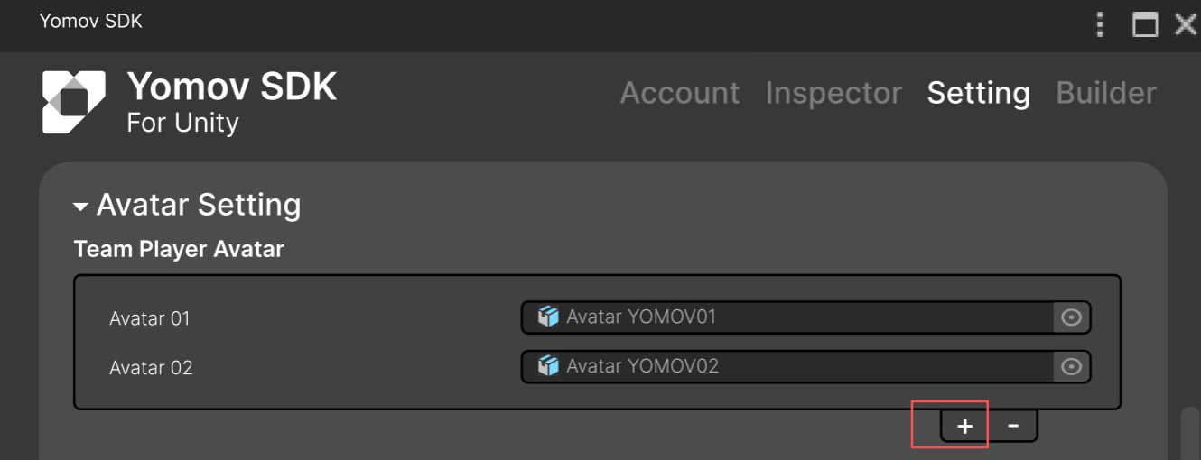
Avatar management: create multiple Team Player avatars
-
-
Non-Team Player Avatars
-
Open YOMOV SDK > Setting > Avatar > NonTeam Player Avatar and click the add button. The SDK creates and configures a Non-Team Player avatar Prefab.
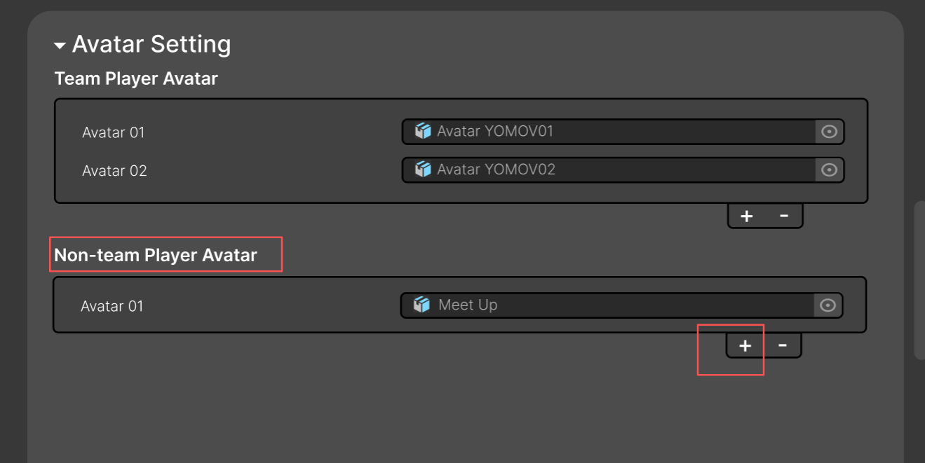
Create a Non-Team Player avatar
-
Bind the avatar model to the Prefab using the same workflow described above.
- Only one Non-Team Player avatar can be created.
Step 4: Configure the Server
The content server application provides two primary capabilities: multiplayer synchronization and bridge-service communication for mixed-content playback and Playback Control System command forwarding.
-
From the YOMOV SDK menu, select Create YOMOVLBEServer. The SDK creates a YOMOVLBEServer Prefab Variant containing the multiplayer server and bridge communication components.
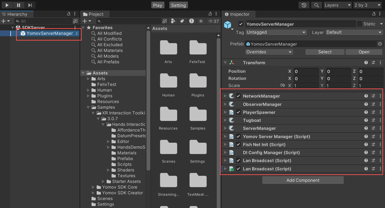
YOMOVLBEServer Prefab Variant
Workflow B: Use a Custom Multiplayer Solution
Integration requirements:
- Applications distributed through the YOMOV LBE VR platform must implement Playback Control System communication, playback authorization, LBE paths, and multi-application bridge communication.
Use this workflow when:
Your VR application implements custom multiplayer gameplay and synchronization.
Your development team can implement and debug the required multiplayer integration.
Step 1: Initial Setup
SDK initialization loads underlying packages and system configuration, connects to the Playback Control System, performs playback authorization, and loads the LBE path. These capabilities form the foundation of YOMOV LBE distribution.
-
In YOMOV SDK > Setting, disable Multiplayer Sync.
-
Multiplayer Sync is enabled by default. Disabling it prevents the application from using YOMOV Multiplayer Sync.
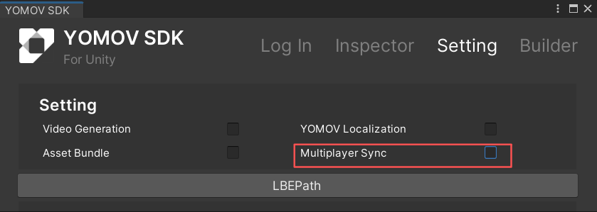
-
-
Add the YOMOV initialization component
-
Open your VR application's initialization scene. From the YOMOV SDK menu, click Create YOMOVInitial.
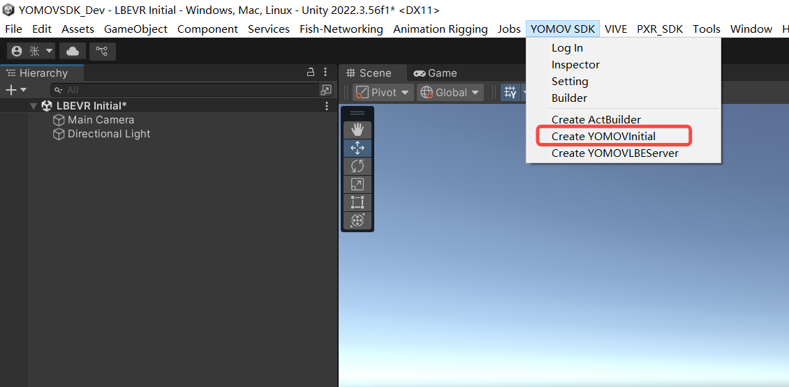
Add YOMOVInitial to the initialization scene
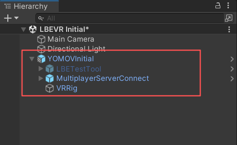
YOMOVInitial added
-
-
Bind XR Origin features
-
Open the generated YOMOVInitial Prefab Variant. Drag the application's XR Origin GameObject under YOMOVInitial > VRRig. We recommend using the hand-interaction variant provided by XRI.
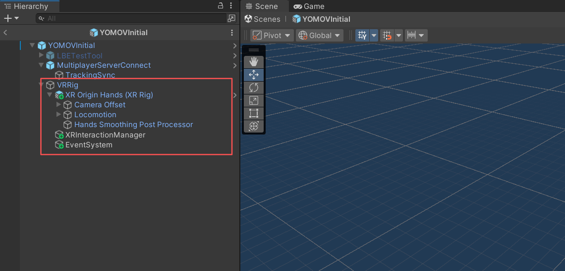
Place XR Origin under the VRRig node
-
Select the VRRig GameObject under YOMOVInitial. In the AddLBEInterator component, click Add LBE Interactor to add the components required for LBE path interaction to XROrigin.
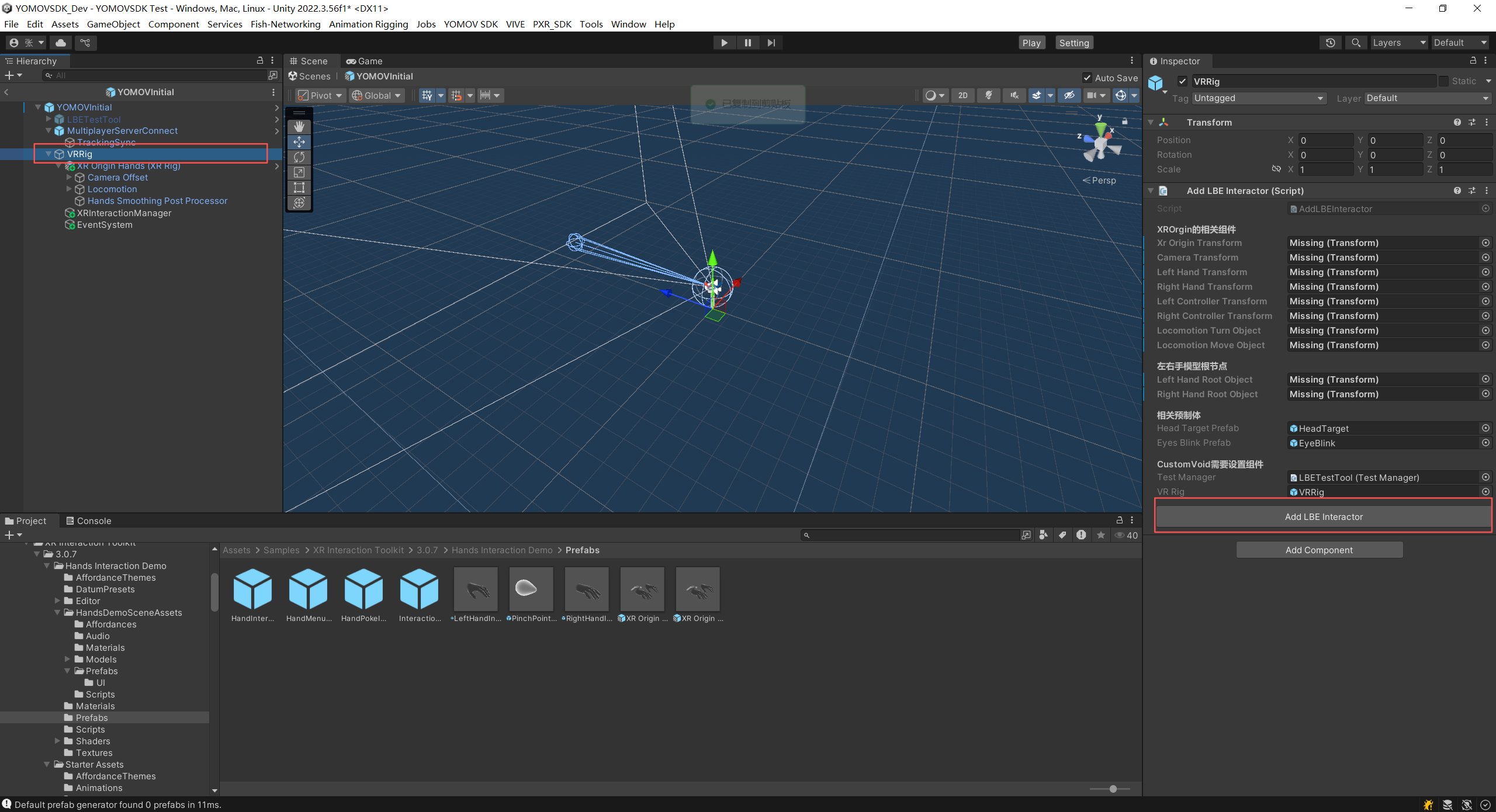
Add LBE Interactor action
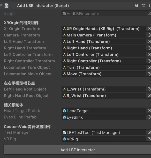
Components added successfully
-
Select the MultiplayerServerConnect GameObject under YOMOVInitial. In the BindXROriginData component, click Bind XROrigin Data to bind XROrigin pose and hand-tracking data to the synchronization components.
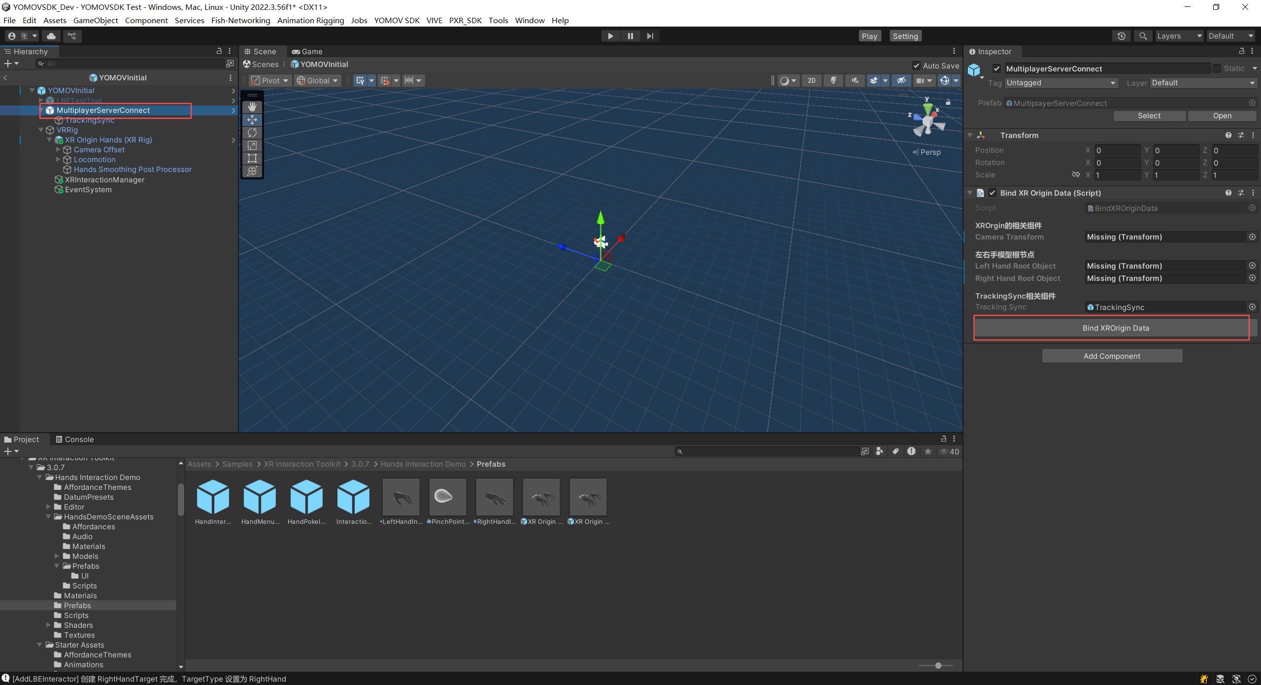
Bind XROrigin Data action
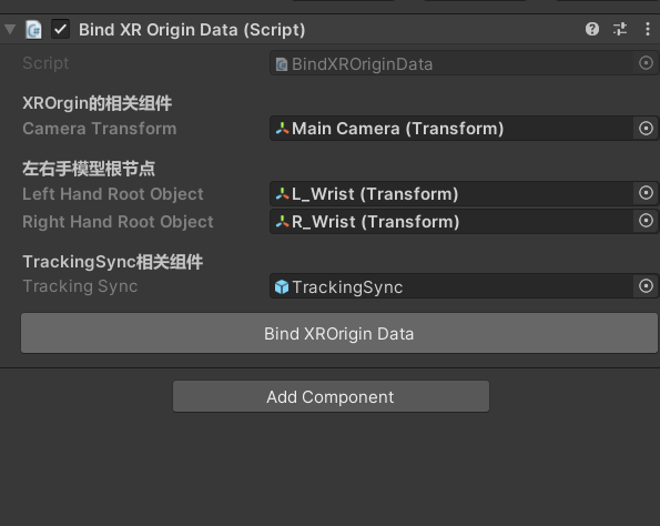
XR Origin data bound successfully
-
YOMOVInitial component reference:
GameObjects | Components | Added By | ||||
|---|---|---|---|---|---|---|
YOMOVInitial
|
| Automatically added | ||||
MultiplayerServerConnect
|
| Automatically added | ||||
LBETestTool
|
| Automatically added | ||||
MenuList | Automatically added | |||||
HandMenuWristButton |
| Automatically added | ||||
SceneSelectManager |
| Automatically added | ||||
TimelineSpeedManager |
| Automatically added | ||||
VRRig |
| Automatically added | ||||
XRInteractionManager |
| Manually added with one click | ||||
EventSystem |
| Manually added with one click | ||||
XROrigin | Created by the developer | |||||
MainCamera | ||||||
HeadTarget |
| Manually added with one click | ||||
Collider |
| Manually added with one click | ||||
EyeBlink |
| Manually added with one click | ||||
Left Controller | ||||||
LeftHandTarget |
| Manually added with one click | ||||
Right Controller | ||||||
RightHandTarget |
| Manually added with one click | ||||
Step 2: Create an LBE Path
See Workflow A > Create an LBE Path.
Step 3: Configure the Server
The content server application normally provides two capabilities: multiplayer synchronization and bridge-system communication for mixed-content playback and Playback Control System commands. In this workflow, you only need to integrate multi-application bridge communication.
-
If the application uses another multiplayer service, locate the BridgeClient example under YOMOVCore > Sample. Adapt this example to implement communication between your content server and the YOMOV bridge server.
- For the communication example, see the source code included with the SDK.